Floating fastener mounting structure

a technology of mounting structure and fastener, which is applied in the direction of fastening means, sheet joining, mechanical equipment, etc., can solve the problems of insufficient structural strength between the mounting socket a and the metal panel member b, affecting the re-installation operation, and the screw of the fastening device may fall from the metal panel member, etc., to achieve the effect of high shearing strength

Active Publication Date: 2017-08-29
HANWIT PRECISION IND LTD
View PDF35 Cites 2 Cited by
  • Summary
  • Abstract
  • Description
  • Claims
  • Application Information

AI Technical Summary

Benefits of technology

[0009]The present invention has been accomplished under the circumstances in view. It is therefore the main object of the present invention to provide a floating fastener mounting structure, which comprises a metal panel member, a mounting socket affixed to the metal panel member, a locking member mounted in the mounting socket and insertable into a locating hole in an external metal panel member to lock the metal panel member to the external metal panel member, and a spring member mounted in the mounting socket to floatably support the locking member in the mounting socket. The mounting socket comprises a center hole vertically extending through opposing top and bottom surfaces thereof, an annular step extended around the periphery thereof at a selected elevation, a stop flange extended around the periphery thereof in flush with the bottom surface of the mounting socket, and a locating groove extended around the periphery thereof between the annular step and said stop flange. Further, the outer diameter of the stop flange is larger than the outer diameter of the annular step. The locking member comprises a shank inserted through the center hole of the mounting socket, a mounting head located at a top end of the shank and extended out of the top surface of the mounting socket, and an expanded locking end tip located at an opposing bottom end of the shank. The spring member is mounted around the shank of the locking member and stopped between a part of the mounting socket and a part of the locking member. The cap member is affixed to said mounting head of the locking member, comprising an accommodation chamber that accommodates a part of the mounting socket and a part of the locking member. Further, the outer diameter of the cap member is equal to or smaller than the outer diameter of the annular step of the mounting socket. The metal panel member comprises a mounting through hole cut through opposing top and bottom surfaces thereof for the insertion of the mounting socket and the cap member therethrough, and a riveting portion formed of a part of the metal panel member around the mounting through hole by stamping and engaged into the annular locating groove of the locking member and wrapped about the stop flange of the mounting socket to affix the mounting socket to the metal panel member. By means of riveting the mounting socket to the metal panel member, the floating fastener mounting structure has high shearing strength.
[0010]Further, when fasten the mounting socket and the metal panel member together, attach a negative mold cavity of a stamping die to the annular step of the mounting socket and the cap member to stop a front planar die surface of the stamping die at the top surface of the metal panel member around the mounting through hole, and then operate the stamping press to stamp the negative mold cavity of the stamping die onto the mounting socket and the cap member, causing the front planar die surface of the stamping die around the negative mold cavity to deform a part of the metal panel member around the mounting through hole into a riveting portion and to simultaneously force the riveting portion thus formed into engagement with the annular locating groove of the mounting socket and tightly stopped between the flat bottom stop surface of the annular step and the stop flange. Thus, the deformed riveting portion of the metal panel member is wrapped about the stop flange of the mounting socket to enhance the structural strength of the connection between the mounting socket and the metal panel member. Even if the mounting socket is pulled or forced by an external force after its fixation to the metal panel member, the mounting socket will not fall out of the metal panel member, assuring a high level of structural stability and shear strength.

Problems solved by technology

The lock screws of the fastening devices may fall from the metal panel members and missed easily due to user's negligence during a metal panel member dismounting procedure for the performance of a repair or speed adjustment operation, affecting further re-installation operation.
Due to limited contact surface area between the mounting socket A and the metal panel member B, the structural strength between the mounting socket A and the metal panel member B is not strong enough, and the bottom mounting portion A1 of the mounting socket A may break easily when the mounting socket A is stretched accidentally by an external force.

Method used


Image

  • Floating fastener mounting structure
  • Floating fastener mounting structure
  • Floating fastener mounting structure

Examples


Embodiment Construction

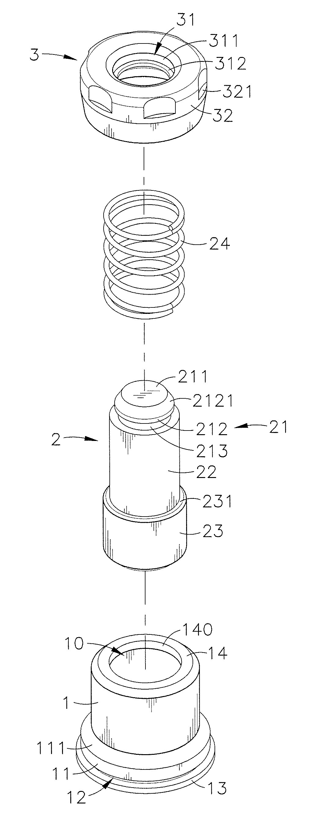
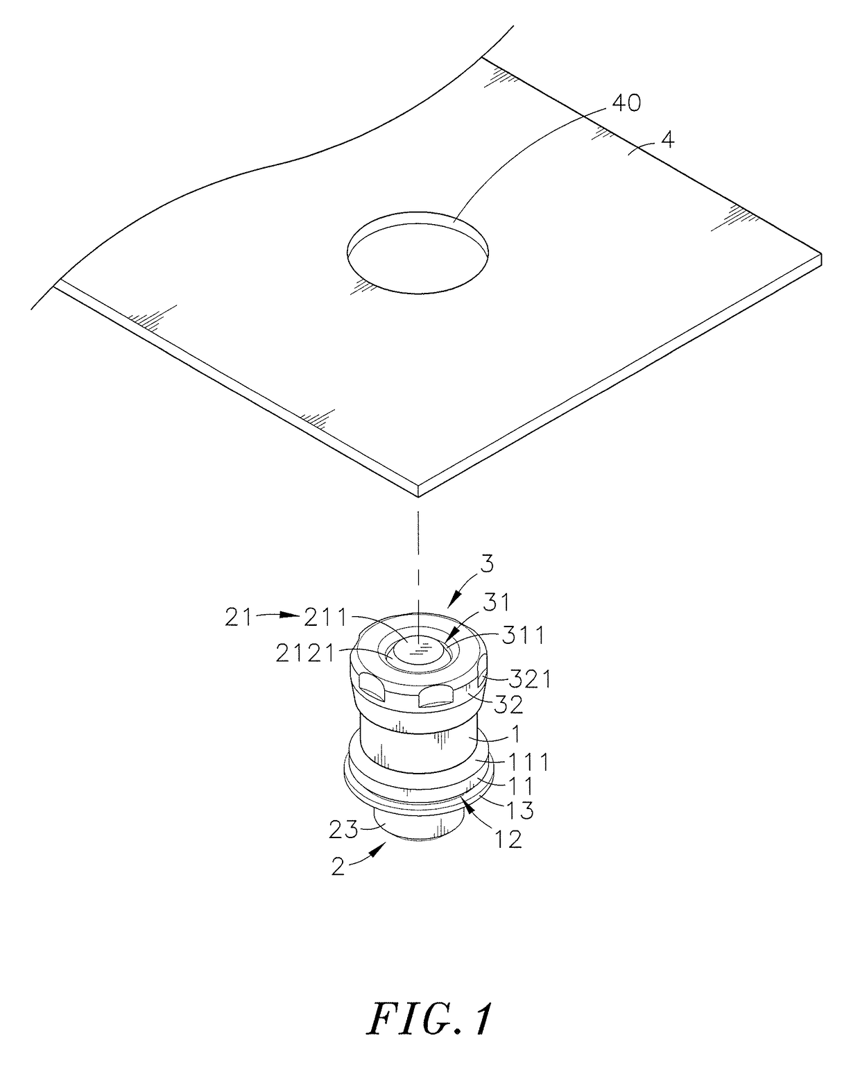
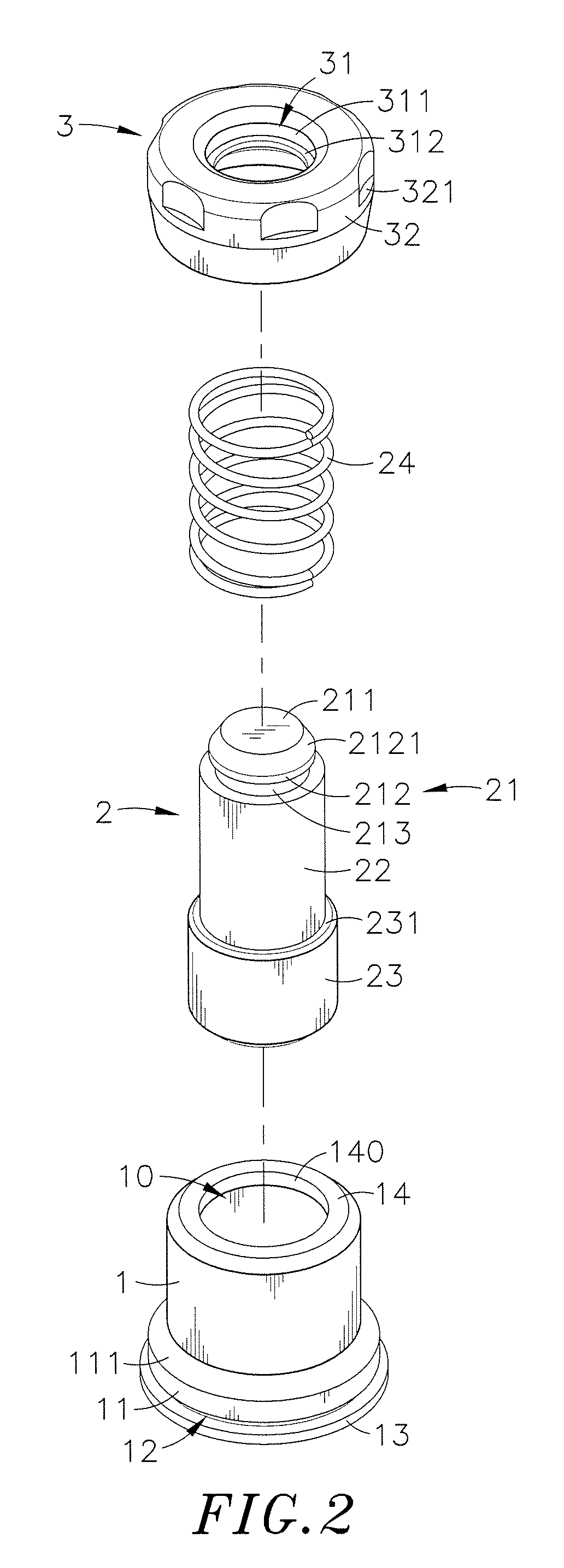
[0022]Referring to FIGS. 1-4, a floating fastener mounting structure in accordance with the present invention is shown. The floating fastener mounting structure comprises a mounting socket 1, a locking member 2, a spring member 24, a cap member 3, and a metal panel member 4.

[0023]The mounting socket 1 is an open-ended cylindrical member comprising a center hole 10 vertically extending through opposing top and bottom sides thereof, an annular step 11 extended around the outer perimeter thereof at a selected elevation and defining a downwardly and outwardly sloping top surface 111 and a flat bottom stop surface 112, a stop flange 13 extended around the outer perimeter in flush with the bottom surface of the mounting socket 1, a locating groove 12 extended around the outer perimeter between the annular step 11 and the stop flange 13, and an annular inner top flange 14 located at a top side of the center hole 10 and defining a bottom abutment surface 141 and a center opening 140 in a co...


PUM

PropertyMeasurementUnit
outer diameteraaaaaaaaaa
strengthaaaaaaaaaa
surface areaaaaaaaaaaa

Abstract

A floating fastener mounting structure includes a mounting socket having a locating groove extending around the periphery and defined between a relatively smaller annular step and a relatively larger stop flange thereof, a metal panel member having a mounting through hole attached to the mounting socket and stopped above the stop flange and stamped by a stamping press to provide a riveting portion and to force the riveting portion to engage into the locating groove and to wrap about the stop flange of the mounting socket, a spring-loaded locking member axially slidably mounted in the mounting socket for detachably locking the metal panel member to an external metal panel member, and a cap member capped on a mounting head of the locking member and affixed to the mounting head during the operation of the stamping press to stamp the metal panel member. Affixing the mounting socket to the metal panel member by riveting greatly enhances the shearing strength of the floating fastener mounting structure.

Description

[0001]This application is a Continuation-In-Part of co-pending application Ser. No. 14 / 614,983, filed on Feb. 5, 2015, which is a Continuation of application Ser. No. 13 / 607,759, filed on Sep. 9, 2012, now abandoned, for which priority is claimed under 35 U.S.C. §120, the entire contents of which are hereby incorporated by reference.BACKGROUND OF THE INVENTION[0002]1. Field of the Invention[0003]The present invention relates to floating fastener mounting technology and more particularly, to a floating fastener mounting structure comprised of a mounting socket, a locking member, a spring member, a cap member and a metal panel member, which enhances the strength of the connected structure between the mounting socket and the metal panel member by means of inserting the mounting socket upwardly inserted with the cap member through a mounting through hole of the metal panel member to let a stop flange of the mounting socket be stopped at the bottom wall of the metal panel member, and usi...

Claims


Application Information

Patent Timeline
Patent Type & Authority Patents(United States)
IPC IPC(8): F16B21/18F16B21/02F16B5/02
CPCF16B21/02F16B5/0208Y10T29/49948
Inventor TSENG, YING-CHIH
Owner HANWIT PRECISION IND LTD
Why Eureka
Try Eureka