
Light sensor calibration system and method

a technology of light sensor and calibration system, which is applied in the field of light sensor, can solve the problems of time-consuming and complex calibration methods of such systems

Active Publication Date: 2017-08-29
CRESTRON ELECTRONICS
View PDF14 Cites 17 Cited by
  • Summary
  • Abstract
  • Description
  • Claims
  • Application Information

AI Technical Summary

Benefits of technology

The technical effects of the patent text are to provide solutions for problems that previously existed with light sensors. These solutions include new methods and modes for the light sensor to improve its performance and minimize issues.

Problems solved by technology

Methods of calibrating such systems can often be complex and time consuming requiring multiple actions at different times by the field engineer to set calibration set points, such as a daytime calibration set point and a nighttime calibration set point.

Method used


Image

  • Light sensor calibration system and method
  • Light sensor calibration system and method
  • Light sensor calibration system and method

Examples


Embodiment Construction

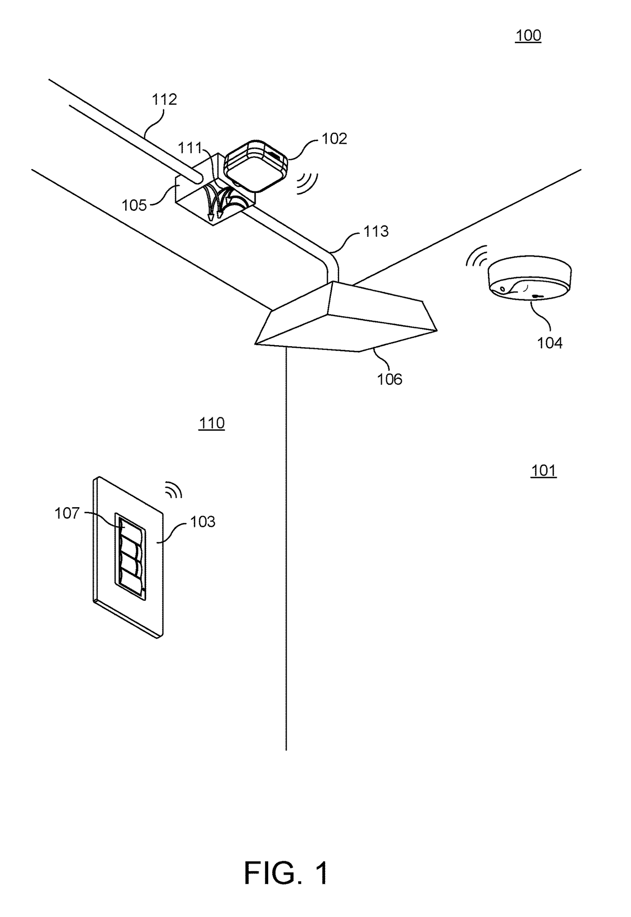
[0033]The embodiments are described more fully hereinafter with reference to the accompanying drawings, in which embodiments of the inventive concept are shown. In the drawings, the size and relative sizes of layers and regions may be exaggerated for clarity. Like numbers refer to like elements throughout. The embodiments may, however, be embodied in many different forms and should not be construed as limited to the embodiments set forth herein. Rather, these embodiments are provided so that this disclosure will be thorough and complete, and will fully convey the scope of the inventive concept to those skilled in the art. The scope of the embodiments is therefore defined by the appended claims. The detailed description that follows is written from the point of view of a control systems company, so it is to be understood that generally the concepts discussed herein are applicable to various subsystems and not limited to only a particular controlled device or class of devices.

[0034]Re...


PUM


Abstract

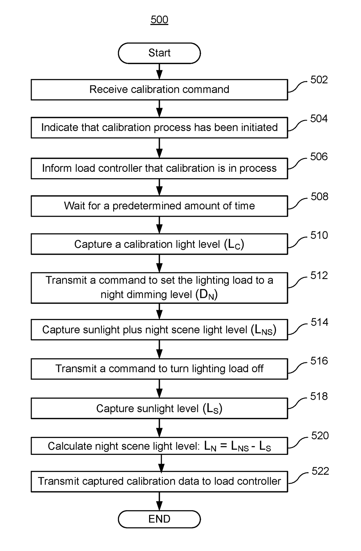
A method and a lighting control system for automatically determining a calibration curve for use in daylight harvesting applications. The lighting control system comprises a light sensor configured for recording light levels and a load controller configured for provide a dimmed output to a lighting load. The calibration curve comprises a calibration slope (SC) defined by a calibration coordinate (CC) and a night coordinate (CN). The calibration coordinate (CC) comprises a calibration dimming level (DC) set by a user and a calibration light level (LC) recorded by the light sensor when the lighting load is set to the calibration dimming level (DC). The night coordinate (CN) comprises a night scene dimming level (DN) and a night scene light level (LN), wherein the night scene light level (LN) comprises a difference between a sunlight plus night scene light level (LNS) recorded by the light sensor when the lighting load is set to the night scene dimming level (DN) and a sunlight level (LS) recorded by the light sensor when the lighting load is turned off.

Description

BACKGROUND OF THE INVENTION[0001]Technical Field[0002]Aspects of the embodiments relate to a light sensor, and more specifically to a light sensor calibration system and method.[0003]Background Art[0004]Efficient and productive use of spaces and resources is an increasingly important goal for businesses and organizations. Given current concerns about energy costs and public perception, this trend should continue for the foreseeable future. Light sensors, or photo sensors, are a crucial component in realizing this goal.[0005]Light sensors are a common component in many buildings. Typically mounted on ceilings, light sensors detect light levels within an area. They are most commonly used to control the power delivered to electrical loads, specifically lights, depending on the detected light levels of the monitored area. Commercial building spaces often require daylight harvesting whereby artificial light sources are reduced in brightness as the amount of sunlight entering the space in...

Claims


Application Information

Patent Timeline
Patent Type & Authority Patents(United States)
IPC IPC(8): H05B37/02G01J1/44G01J1/42H05B33/08H05B44/00
CPCG01J1/44H05B37/0218H05B33/0854H05B37/0227H05B37/0272G01J1/4204G01J2001/444G01J1/18G01J1/32G01J1/0228H05B47/11H05B47/19Y02B20/40H05B47/105H05B45/12
Inventor KUMAR, RUSSIKESH
Owner CRESTRON ELECTRONICS
Learn More