
Switched reversing configuration control for string instruments and boost circuit therefor

Active Publication Date: 2017-08-29
MICEK PETR
View PDF65 Cites 5 Cited by
  • Summary
  • Abstract
  • Description
  • Claims
  • Application Information

AI Technical Summary

Benefits of technology

This patent describes a circuit that can increase the amplitude of a string instrument's signals by using two pickup sensors with opposite polarity. The circuit also includes an attenuation circuit that can reduce signals from one pickup sensor while boosting those from the other. This results in a stronger overall signal from the pair of pickup sensors.

Problems solved by technology

The signal generated by most pickup sensors are of insufficient strength to directly drive an audio transducer, such as a loudspeaker, so they must be amplified prior to being input to the audio transducer.
Because of their natural inductive qualities, all magnetic pickups tend to pick up ambient electromagnetic interference (EMI) from electrical power wiring in the vicinity, such as the wiring in a building.
The EMI from a 50 or 60 Hz power system can result in a noticeable “hum” in the amplified audio by from the audio transducer, particularly with poorly shielded single-sensor pickups.
Using a passive boost circuit to reduce the amplitude of the signals from the reversed polarity sensor reduces the subtractive effect and results in a stronger sound, but still with some muting of the lower frequencies.

Method used


Image

  • Switched reversing configuration control for string instruments and boost circuit therefor
  • Switched reversing configuration control for string instruments and boost circuit therefor
  • Switched reversing configuration control for string instruments and boost circuit therefor

Examples


Embodiment Construction

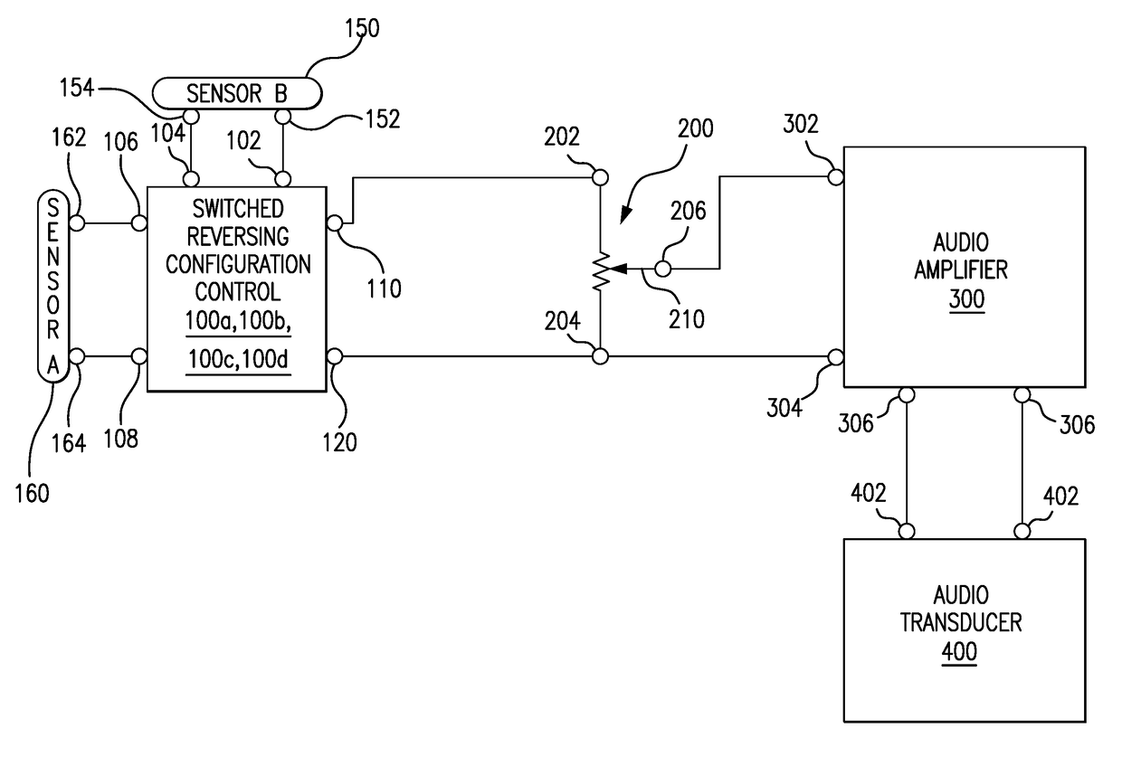
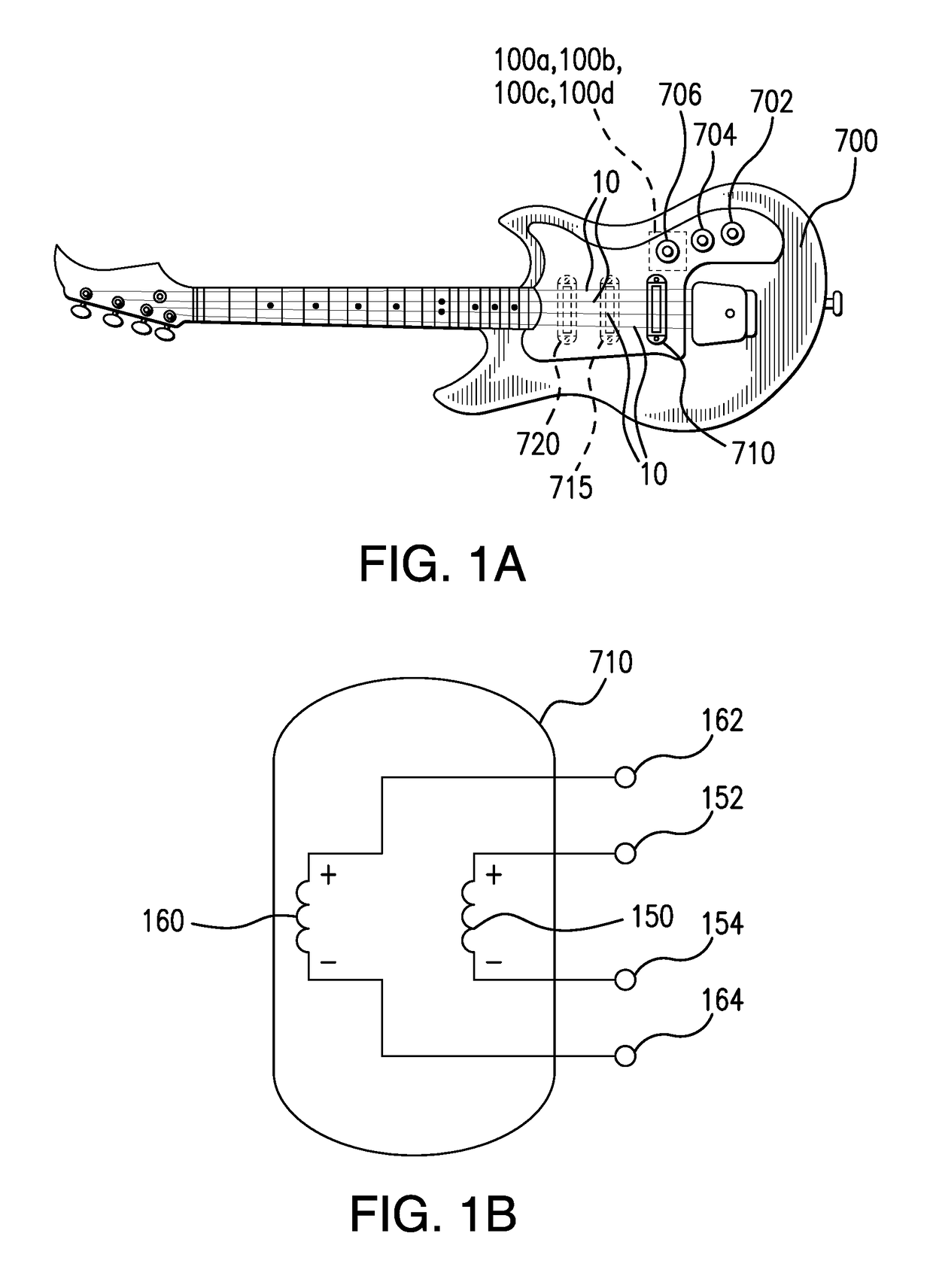
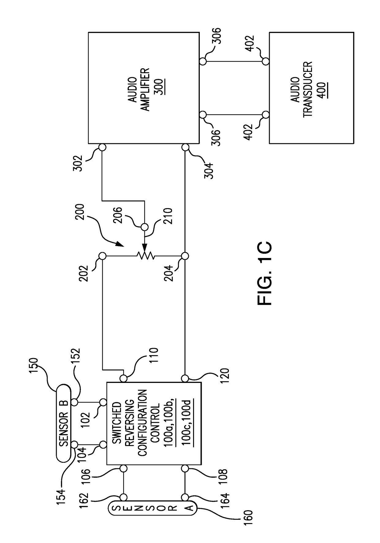
[0030]Referring to FIGS. 1A-5C, there is shown switched reversing configuration control 100a, 100b, 100c, 100d for use with an electric string instrument. Switched reversing configuration control 100a, 100b, 100c, 100d provides selective variation the electrical configuration of a pair of pickup sensors 150 and 160 between being connected with their polarity being in common in one of series or parallel, effectively providing the output of a single one of the pickup sensors, and being connected with the polarity of one pickup sensor having an opposite polarity respect to the other while being in one of series or parallel.

[0031]As used herein the terms “like polarity,”“common polarity,”“polarity in common,”“same polarity” and the like all refer to the pickup sensor property known as phase, where the two pickup sensor outputs are in-phase (have the same phase). The phase property of a pickup sensor is a designation of the direction that current flows through that sensor and usually ind...


PUM


Abstract

A switched reversing configuration control for string instruments connects to a pair of pickup sensors located on an electric string instrument for selectively electrically configuring the pickup sensors between (a) the pair of pickup sensors being coupled with like polarity in one of series or parallel with respect to a pair of output terminals, or (b) effectively coupling only one of the pair of pickup sensors to the output terminals, or (c) the pair of pickup sensors being coupled with opposing polarity in one of series or parallel with respect to the output terminals. An optional reverse polarity passive boost circuit is provided for increasing the output voltage coupled to the output terminals when the pickup sensors are coupled with opposing polarity as compared to the output voltage that would otherwise be provided absent the reverse polarity passive boost circuit.

Description

BACKGROUND OF THE INVENTION[0001]This disclosure directs itself to a reversing configuration control for electric string instruments and a boost circuit usable therewith. The reversing configuration control permits switching between various combinations of a pair of pickup sensors, either widely separated or collocated in a common enclosure, in one of series or parallel with the pickup sensors being of like polarity, a single one of the pickup sensors, and in one of series or parallel with the pickup sensors being of opposite polarity, one with respect to the other. More in particular, the disclosure is directed to a reversing configuration control for string instruments that includes a pair of pickup sensors disposed on a string instrument in which voltages are output by the sensors responsive to vibration of at least one string of the string instrument and a multipole switch providing selective operative coupling of the pair of pickup sensors in various configurations to the outpu...

Claims


Application Information

Patent Timeline
IPC IPC(8): G10H3/18
CPCG10H3/186G10H3/182G10H2220/505
Inventor MICEK, PETR
Owner MICEK PETR
Learn More