Supercharge Your Innovation With Domain-Expert AI Agents!

Electrostatic atomization system for vehicle

a technology of electrostatic atomization and vehicle, which is applied in the direction of electrostatic spraying apparatus, burners, vehicle components, etc., can solve the problems of drinking water flowing into damage to the electrostatic atomization device,

Active Publication Date: 2017-09-05
PANASONIC INTELLECTUAL PROPERTY MANAGEMENT CO LTD
View PDF18 Cites 2 Cited by
  • Summary
  • Abstract
  • Description
  • Claims
  • Application Information

AI Technical Summary

Benefits of technology

This configuration effectively prevents liquids from flowing back into the electrostatic atomization device, protecting it from damage while maintaining the concentration and emission efficiency of charged micro-particle water, ensuring effective deodorization and allergenic substance suppression without dilution by the air conditioner airflow.

Problems solved by technology

This may damage the electrostatic atomization device.
In this case, drinking water may also flow into the electrostatic atomization device and damage it.

Method used


Image

  • Electrostatic atomization system for vehicle
  • Electrostatic atomization system for vehicle
  • Electrostatic atomization system for vehicle

Examples


Embodiment Construction

[0018]One embodiment of an electrostatic atomization system for a vehicle will now be described with reference to the drawings.

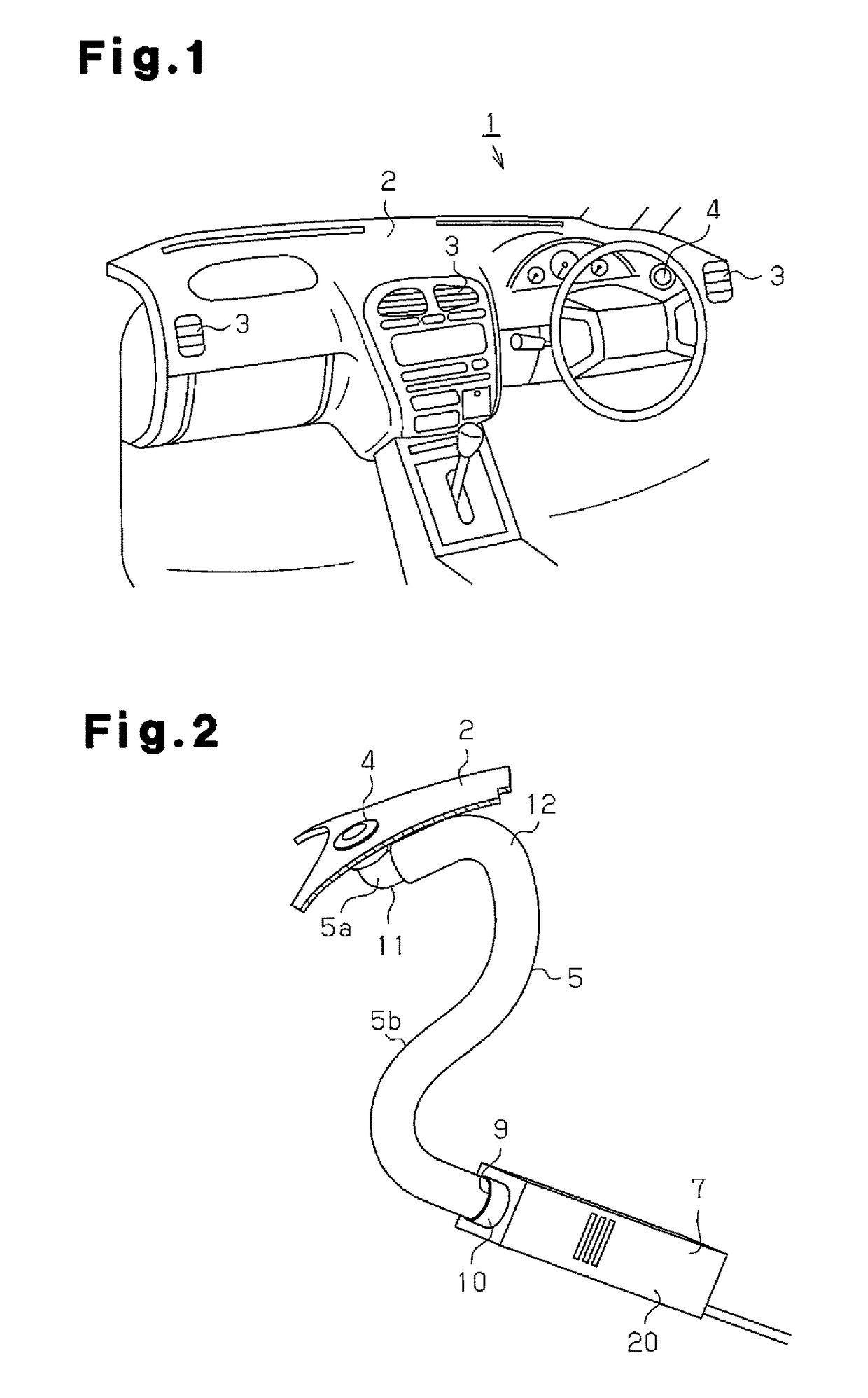
[0019]FIG. 1 illustrates an interior of a vehicle when seen from the rear seat to the front. Air outlets 3 are formed in the center position and both right and left side positions of an instrument panel 2 arranged in a front side of a vehicle interior 1. Each of the air outlets 3 is connected to an air conditioner not illustrated via an air flow path not illustrated which is piped to the instrument panel 2. The air blown from the air conditioner is emitted from each of the air outlets 3 into the vehicle interior 1 via the air flow path.

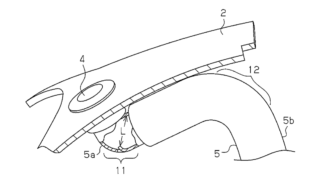
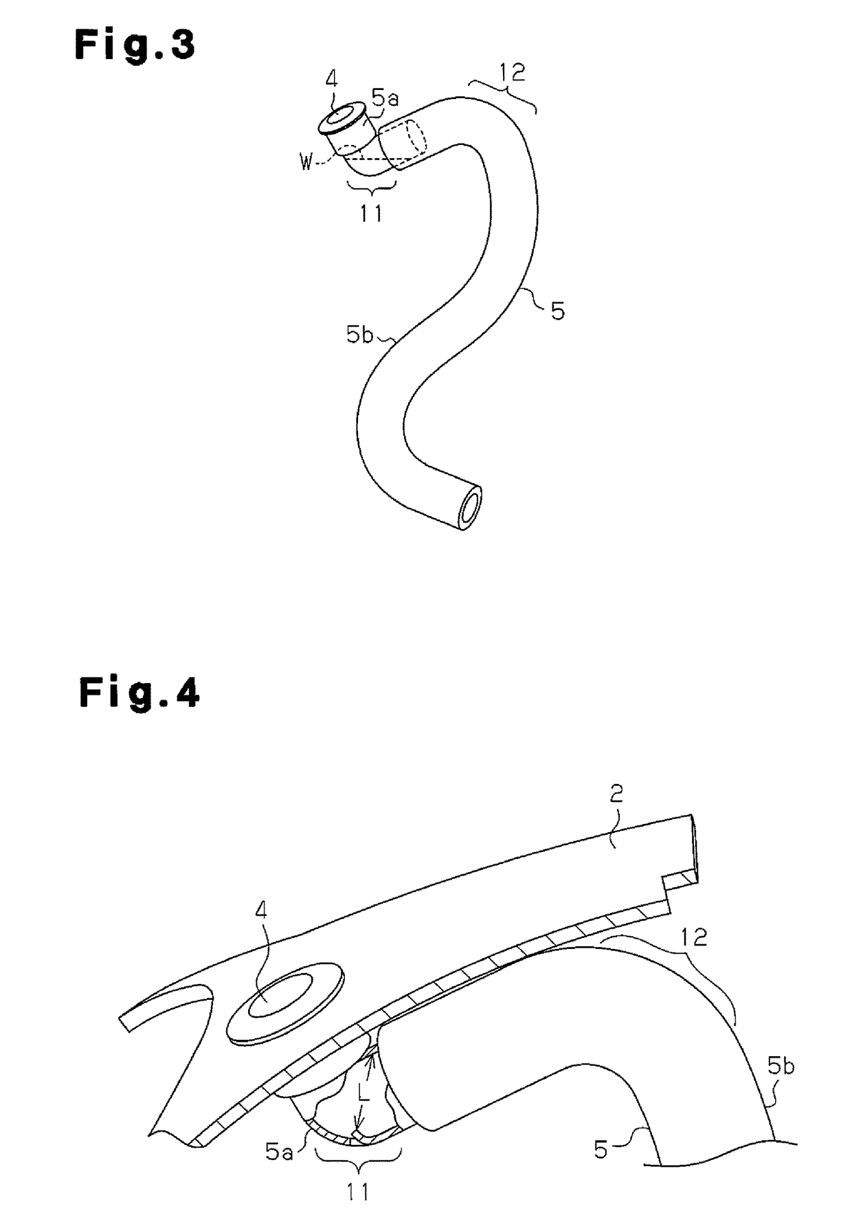
[0020]A vehicle interior introduction port 4 is formed in a position adjacent to the air outlet 3 arranged on the driver seat side in the instrument panel 2. As illustrated in FIG. 2, the vehicle interior introduction port 4 is connected to an electrostatic atomization device 7, which is arranged in a lower position than the v...


PUM


Abstract

An electrostatic atomization system for a vehicle includes an electrostatic atomization device that generates and emits charged micro-particle water from an emission port, a vehicle interior introduction port arranged in an instrument panel in a vehicle interior, and a communication duct that connects the emission port and the vehicle interior introduction port to emit the charged micro-particle water from the vehicle interior introduction port to the vehicle interior. The communication duct includes a first curved portion, which is arranged between the emission port and the vehicle interior introduction port and curved downward in a lower position than the vehicle interior introduction port, and a second curved portion, which is arranged between the first curved portion and the emission port and curved upward in an upper position than the first curved portion.

Description

RELATED APPLICATIONS[0001]This application is the U.S. National Phase under 35 U.S.C. §371 of International Application No. PCT / JP2011 / 070252, filed on Sep. 6, 2011, which in turn claims the benefit of Japanese Application No. 2010-213518, filed on Sep. 24, 2010, the disclosures of which Applications are incorporated by reference herein.TECHNICAL FIELD[0002]The present invention relates to an electrostatic atomization system for a vehicle.BACKGROUND ART[0003]An electrostatic atomization device has been mounted on a vehicle in order to remove odor absorbed in a seat and suppress allergenic substances brought into the vehicle interior by a person getting on / off the vehicle (for example, Patent Document 1). The electrostatic atomization device is connected to an air conditioning duct and emits charged micro-particle water generated in a nanometer size to the vehicle interior via the air conditioning duct. Charged micro-particle water emitted into the vehicle interior removes the odor a...

Claims


Application Information

Patent Timeline
Patent Type & Authority Patents(United States)
IPC IPC(8): B05B5/00B60H3/00B05B5/025B05B5/057
CPCB60H3/0071B05B5/025B05B5/0255B05B5/057
Inventor YANO, TAKESHISUGAWA, AKIHIDE
Owner PANASONIC INTELLECTUAL PROPERTY MANAGEMENT CO LTD
Features
  • R&D
  • Intellectual Property
  • Life Sciences
  • Materials
  • Tech Scout
  • Unparalleled Data Quality
  • Higher Quality Content
  • 60% Fewer Hallucinations
Learn More