Rotor blade for a wind power plant

a technology for wind power plants and rotor blades, which is applied in the direction of sustainable buildings, machines/engines, mechanical equipment, etc., can solve the problems of large weight of rotor blades, complicated and difficult production and transportation to respective erection locations, and the implementation of rotor blades, so as to reduce the load on the machine structure and the pylon, the maximum level of stiffness is achieved, and the weight is low

Active Publication Date: 2017-09-12
WOBBEN PROPERTIES GMBH
View PDF22 Cites 7 Cited by
  • Summary
  • Abstract
  • Description
  • Claims
  • Application Information

AI Technical Summary

Benefits of technology

[0006]One or more embodiments of the present invention provides a rotor blade which is of low weight with a maximum level of stiffness, by which the loads on the machine structure and the pylon are reduced, and which is simple to transport. The invention seeks at least to propose an alternative solution.
[0008]The relative profile thickness has a local maximum between the rotor blade root and the rotor blade tip. The local maximum is in the central region between the rotor blade root and the rotor blade tip, preferably in a region of 30 to 60% of the total length of the rotor blade, measured from the rotor blade root to the rotor blade tip. With a total length of for example 60 meters, the local maximum is thus in a region of preferably 18 meters to 36 meters. The relative profile thickness thus initially falls, starting from the rotor blade root, and then rises in the central region again to the local maximum, namely to a location, in the area surrounding which the relative profile thickness does not involve a higher value. The local maximum in the central region of the rotor blade is afforded in particular by the profile depth decreasing greatly from the rotor blade root to the central region. At the same time or alternatively the profile thickness can be increased or may not decrease as greatly as the profile depth. That achieves a saving on material, in particular between the rotor blade root and the central region, and thus a saving in weight. A high level of stability is achieved for the rotor blade by the increase in profile thickness.
[0013]Assembling the rotor blade from two rotor blade portions provides that transport of the rotor blade to the appropriate erection location of the wind power installation is considerably facilitated. If the separation location is in the central region, that means, with a rotor diameter of over 80 meters, that for example there are only still two rotor blade portions each of about 40 that have to be transported. In addition, in the central region and / or in the region of the local maximum of the relative profile thickness, in particular the profile depth is small with a large profile thickness. As a result, the rotor blade is of a stable configuration at that location. The additional loadings occurring due to the separation location are thus very substantially absorbed.
[0016]Such a reduced profile depth in the region of the rotor blade tip reduces loads acting on the machine structure and the pylon, in particular aerodynamic loads. Basically a comparatively slender rotor blade is proposed.

Problems solved by technology

In the case of such large wind power installations and thus also very large rotor blades, that results in the rotor blade being of a great weight.
In addition production and transport to the respective erection locations is complicated and difficult.
Implementation of a rotor blade which is divided into two and which would be more appropriate for transport of such large rotor blades is however only limitedly possible, because of the loads which occur and because of the reduction in stability which additionally occurs due to the separation location.

Method used


Image

  • Rotor blade for a wind power plant
  • Rotor blade for a wind power plant
  • Rotor blade for a wind power plant

Examples


Embodiment Construction

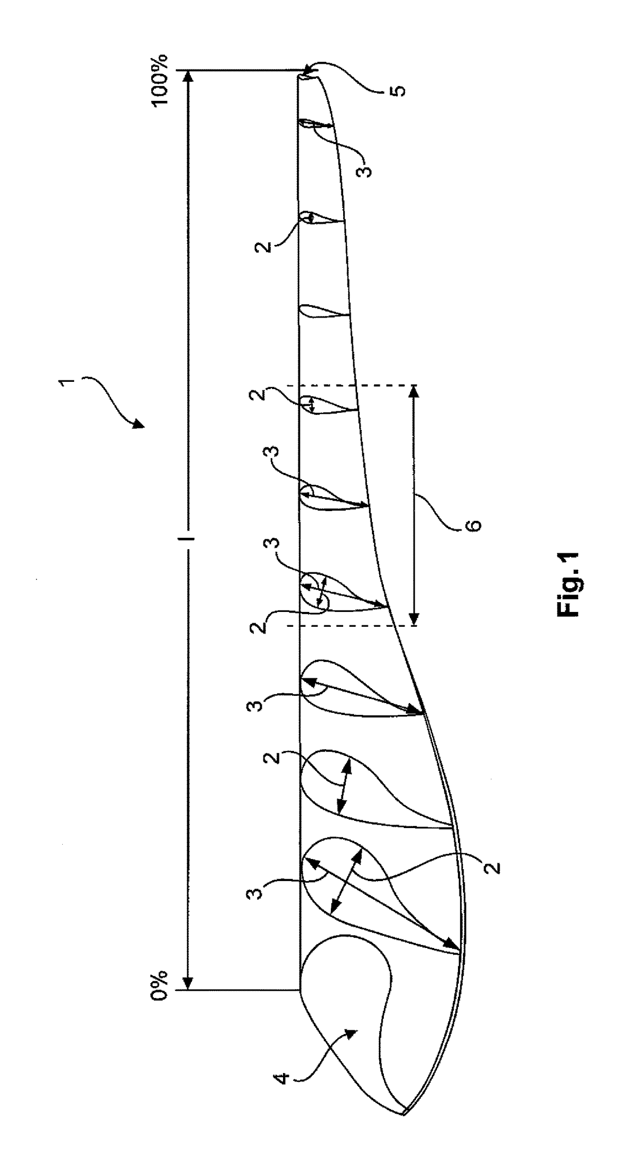
[0028]FIG. 1 shows a distribution of various profile geometries of a rotor blade 1 of an embodiment. Profile thicknesses 2 and profile depths 3 are shown in portion-wise manner in the rotor blade 1. The profile depths 3 measure the depth of the rotor blade from a curved edge (foreground) to a substantially flat edge (background). The profile thickness 2 measures the thicknesss of the rotor blade in vertical planes of the page. At one end the rotor blade 1 has the rotor blade root 4 and at the end remote therefrom it has a connecting region 5 for the attachment of a rotor blade tip. At the rotor blade root 4 the rotor blade has a large profile depth 3. In the connecting region 5 in contrast the profile depth 3 is very much smaller. The profile depth decreases markedly from the rotor blade root 4 which can also be referred to as the profile root 4, to a central region 6. A separation location (not shown here) can be provided in the central region 6. The profile depth 3 is almost const...


PUM


Abstract

The invention concerns a rotor blade of a wind power installation, comprising a rotor blade root (4) for attachment of the rotor blade to a rotor hub and a rotor blade tip arranged at a side remote from the rotor blade root, as well as a wind power installation having such rotor blades. In that arrangement a relative profile thickness which is defined as the ratio of profile thickness to profile depth has a local maximum in a central region between rotor blade root and rotor blade tip.

Description

BACKGROUND[0001]Technical Field[0002]The invention concerns a rotor blade of a wind power installation, and a wind power installation.[0003]Description of the Related Art[0004]Rotor blades for wind power installations are generally known. Such rotor blades have a profile which takes into account the particular aerodynamic demands. Usually a wind power installation has an aerodynamic rotor with a plurality of rotor blades. Such a wind power installation is shown by way of example in FIG. 5. The aerodynamic properties of such rotor blades are crucial as they greatly influence the operational efficiency of the rotor blades and thus the wind power installation. The profiles are optimized to increase the operational efficiency of the rotor blades. To ensure current production which is as steady as possible for example in regions involving a light wind, more specifically in particular at on-shore locations, the aerodynamic rotor blades are of a rotor diameter which can be more than 80 met...

Claims


Application Information

Patent Timeline
Patent Type & Authority Patents(United States)
IPC IPC(8): F03D1/06F03D13/10
CPCF03D1/0675F03D1/065F03D1/0633F03D1/0641F03D13/10F05B2240/302Y02E10/721Y02B10/30Y02E10/72F03D1/06
Inventor BOHLEN, THOMAS
Owner WOBBEN PROPERTIES GMBH
Why Eureka
Try Eureka