Heat exchanger

a heat exchanger and heat exchanger technology, applied in indirect heat exchangers, lighting and heating apparatus, separation processes, etc., can solve the problems of large oil separator cost, large refrigerant charge, and large refrigerant charge, so as to reduce the amount of refrigerant charge and good heat exchanger performance

Active Publication Date: 2017-09-12
DAIKIN IND LTD
View PDF25 Cites 6 Cited by
  • Summary
  • Abstract
  • Description
  • Claims
  • Application Information

AI Technical Summary

Benefits of technology

[0009]With the conventional technique, an oil separator is provided behind a compressor to secure the performance of an evaporator in a refrigerating cycle in which a small amount of oil is flowed out from the compressor. In this system, the following methods have been employed: (1) Using a large oil separator and a flooded type; (2) Using a small oil separator and a hybrid falling film type. In (1), the cost of the large oil separator is high. In (2), the amount of the refrigerant can be reduced by the falling film type. However, since a lot of flooded sections are needed, the effect of reducing the refrigerant amount will be diminished. Also, a lot of heat transfer pipes are needed to condense oil.
[0017]In view of the above, one object of the present invention is to provide a heat exchanger that can reduce the amount of refrigerant charge while ensuring good performance of the heat exchanger.

Problems solved by technology

The hybrid falling film evaporator disclosed in U.S. Pat. No. 5,839,294 as mentioned above still presents a problem that it requires a relatively large amount of refrigerant charge because of the existence of the flooded section at the bottom portion of the shell.
Therefore, performance of the evaporator is degraded.
In (1), the cost of the large oil separator is high.
However, since a lot of flooded sections are needed, the effect of reducing the refrigerant amount will be diminished.
Also, a lot of heat transfer pipes are needed to condense oil.
Since the oil is returned to the compressor together with the refrigerant, if the amount of the returned refrigerant is large, an invalid refrigerant is increased.
Then, the performance will be deteriorated.

Method used


Image

  • Heat exchanger
  • Heat exchanger
  • Heat exchanger

Examples


first embodiment

Modification of First Embodiment

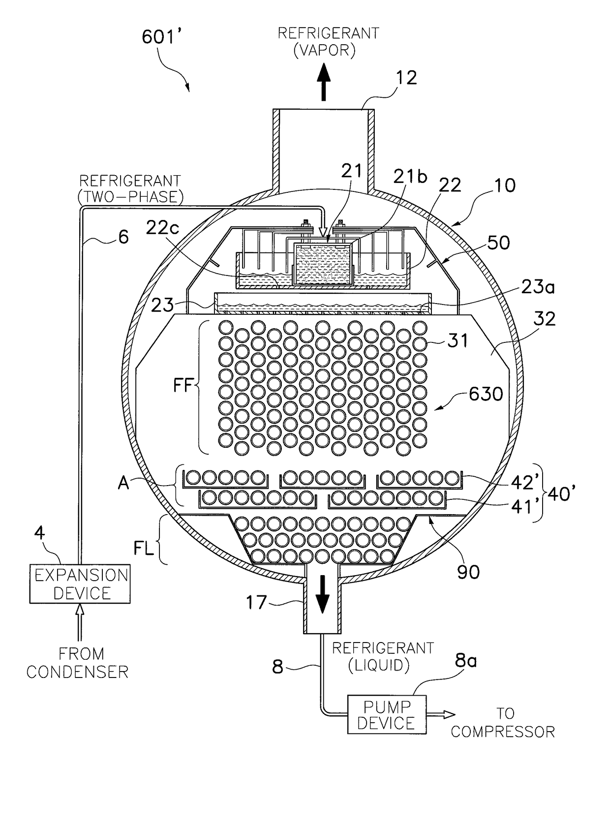
[0106]Referring now to FIGS. 13-16, an evaporator 1′ is illustrated in accordance with a modification of the first embodiment. The evaporator 1′ is identical to the evaporator 1, except the evaporator includes a modified trough part 40′. In view of the similarity between this modification of the first embodiment and the first embodiment, the parts of this modification of the first embodiment that are identical to the parts of the first embodiment will be given the same reference numerals as the parts of the first embodiment. Moreover, the descriptions of the parts of this modification of the first embodiment that are identical to the parts of the first embodiment may be omitted for the sake of brevity. Moreover, it will be apparent to those skilled in the art from this disclosure that the descriptions and illustrations of the preceding embodiment also apply to this modification of the first embodiment, except as explained and illustrated herein.

[0107]...

second embodiment

Modification of Second Embodiment

[0110]Referring now to FIG. 18, an evaporator 201′ is illustrated in accordance with a modification of the second embodiment. The evaporator 201′ is identical to the evaporator 201, except the evaporator includes a modified trough part 240′. In view of the similarity between this modification of the second embodiment and the second embodiment, the parts of this modification of the second embodiment that are identical to the parts of other embodiments will be given the same reference numerals as the parts of the other embodiments. Moreover, the descriptions of the parts of this modification of the second embodiment that are identical to the parts of the other embodiments may be omitted for the sake of brevity. Moreover, it will be apparent to those skilled in the art from this disclosure that the descriptions and illustrations of the preceding second embodiment also apply to this modification of the second embodiment, except as explained and illustrat...

third embodiment

[0112]Referring now to FIG. 19, an evaporator 301 in accordance with a third embodiment will now be explained. This third embodiment is identical to the first embodiment, except this third embodiment includes a modified trough part 340. Therefore, the descriptions and illustrations of the first embodiment also apply to this third embodiment, except as discussed and illustrated herein. In view of the similarity between the third embodiment and the first embodiment, the parts of the sixth embodiment that are identical to the parts of the first embodiment will be given the same reference numerals. Moreover, the descriptions of the parts of the third embodiment that are identical to the parts of the other embodiments may be omitted for the sake of brevity. As just mentioned, the evaporator 301 in accordance with this third embodiment is identical to the evaporator 1 of the first embodiment, except the evaporator 301 includes a modified trough part 340. Specifically, the modified trough ...


PUM

PropertyMeasurementUnit
velocityaaaaaaaaaa
velocityaaaaaaaaaa
vertical heightsaaaaaaaaaa

Abstract

A heat exchanger for a vapor compression system includes a shell, a distributing part disposed inside of the shell to distribute a refrigerant, a tube bundle and a trough part. The tube bundle includes a plurality of heat transfer tubes disposed inside of the shell below the distributing part. The tube bundle includes a falling film region disposed below the distributing part, an accumulating region disposed below the falling film region, and a flooded region disposed below the accumulating region at a bottom portion of the shell. The trough part extends under at least one of the heat transfer tubes in the accumulating region to accumulate the refrigerant therein. The trough part at least partially overlaps with the at least one of the heat transfer tubes in the accumulating region when viewed along a horizontal direction perpendicular to the longitudinal center axis of the shell.

Description

BACKGROUND OF THE INVENTION[0001]Field of the Invention[0002]This invention generally relates to a heat exchanger adapted to be used in a vapor compression system. More specifically, this invention relates to a heat exchanger including a tube bundle with a falling film region, an accumulating region and a flooded region.[0003]Background Information[0004]Vapor compression refrigeration has been the most commonly used method for air-conditioning of large buildings or the like. Conventional vapor compression refrigeration systems are typically provided with an evaporator, which is a heat exchanger that allows the refrigerant to evaporate from liquid to vapor while absorbing heat from liquid to be cooled passing through the evaporator. One type of evaporator includes a tube bundle having a plurality of horizontally extending heat transfer tubes through which the liquid to be cooled is circulated, and the tube bundle is housed inside a cylindrical shell. There are several known methods f...

Claims


Application Information

Patent Timeline
Patent Type & Authority Patents(United States)
IPC IPC(8): F28D5/02F25B39/02F28D3/00B01D5/00F28D7/16F28D21/00
CPCF25B39/028F28D5/02F28D7/16F28D7/163F25B2339/024F28D2021/0064F28D2021/0071
Inventor NUMATA, MITSUHARUKASAI, KAZUSHIGE
Owner DAIKIN IND LTD
Why Eureka
Try Eureka