Flyback converter with no need for the auxiliary winding

a technology of auxiliary windings and converters, applied in the field of flyback converters, can solve the problems of loose output voltage regulation and other problems, and achieve the effect of reducing leakage inductance and enhanced magnetic coupling

Active Publication Date: 2017-09-12
INNOTECH CO LTD
View PDF5 Cites 7 Cited by
  • Summary
  • Abstract
  • Description
  • Claims
  • Application Information

AI Technical Summary

Benefits of technology

[0020]The switching unit, connected in series with the current-sensing resistor, placed at the high side of the primary winding, and driven by the GATE pin of the PWM controller, can be but won't be limited to a power Metal Oxide Semiconductor Field Effect Transistor (MOSFET) or a power Bipolar Junction Transistor (BJT). The GND pin of the PWM controller must be connected / referenced to the source / emitter of the power MOSFET / BJT through the current-sensing resistor in order to high-side drive the switching unit with a source / emitter-referenced PWM signal.
[0021]The AF flyback transformer simply comprises a primary winding and a secondary winding, where the primary winding is split into two halves, which can be made symmetric / asymmetric, i.e. given equal / unequal turns number, and the secondary winding is sandwiched in between the first half and the second half of the primary winding to enhance the magnetic coupling and reduce the leakage inductance of the AF flyback transformer. The first half of the primary winding can lend itself to providing the PWM controller with a continuous and steady working voltage supply after startup in the absence of the auxiliary winding, thus eliminating the need for the auxiliary winding.

Problems solved by technology

PSR regulates the output voltage by means of magnetic coupling to the primary side, requiring no optocoupler-based feedback control circuit in the secondary side while having the disadvantage of a looser output voltage regulation.

Method used


Image

  • Flyback converter with no need for the auxiliary winding
  • Flyback converter with no need for the auxiliary winding
  • Flyback converter with no need for the auxiliary winding

Examples


Embodiment Construction

[0032]The accompanying drawings are included to provide a further understanding of the invention, and are incorporated in and constitute a part of this specification. The drawings illustrate embodiments of the invention and, together with the description, serve to explain the principles of the invention.

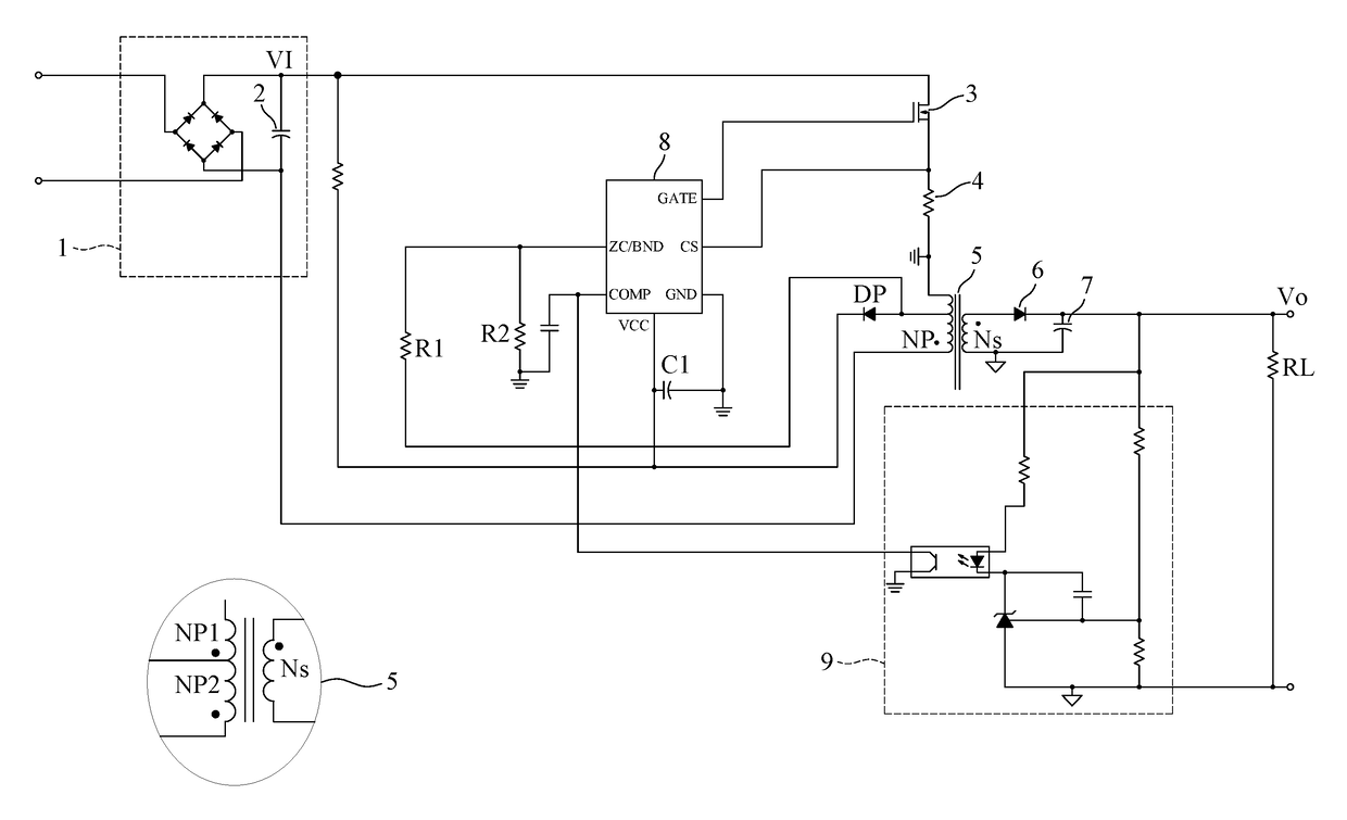
[0033]Since FIG. 4 has a lot in common with FIG. 3 except the PWM controller, which is exemplified with a 6-pin IC (FIG. 3) or an 8-pin IC (FIG. 4), the following paragraphs would shed light only on FIG. 3 to give a clearer picture of the present invention.

[0034]Please refer to FIG. 3 for a novel AF-HSD-SSR flyback converter built around a 6-pin PWM controller as an example according to the present invention. The AF-HSD-SSR flyback converter comprises an AC-to-DC rectification unit 1, an input capacitor 2, a switching unit 3, a current-sensing resistor 4, an Auxiliary-Free (AF) flyback transformer 5, an output rectifier 6, an output capacitor 7, a PWM controller 8, and a SSR unit 9, ...


PUM


Abstract

Disclosed is an Auxiliary-Free High-Side Driven Secondary-Side Regulated (AF-HSD-SSR) flyback converter, which includes an AC-to-DC rectification unit, an input capacitor, a switching unit, a current-sensing resistor, an Auxiliary-Free (AF) flyback transformer, an output rectifier, an output capacitor, a PWM controller, and a SSR unit. The AF flyback transformer includes a primary winding and a secondary winding, where the primary winding is split into two halves. The switching unit is placed at the high side of the primary winding, and the PWM controller in collocation with the SSR unit drives the switching unit in response to all the required voltage and current sense signals to keep voltage conversion and power delivery safe and efficient within the specifications. The first half of the primary winding can provide the PWM controller with a continuous and steady working voltage supply after startup, thus eliminating the need for the auxiliary winding.

Description

BACKGROUND OF THE INVENTION[0001]1. Field of the Invention[0002]The present invention relates to a flyback converter, and more specifically to a flyback converter with no need for the auxiliary winding in the flyback transformer, leading to simplification of transformer structure and reduction in transformer cost.[0003]2. The Prior Arts[0004]Various DC-powered devices, such as integrated circuits, DC motors, or liquid crystal displays without a proper DC voltage source, would need a suitable voltage converter, such as a flyback converter, a forward converter, or an LLC converter for DC-to-DC voltage conversion, to convert a rectified AC voltage source to a specified DC voltage level to power them.[0005]In prior arts, a flyback converter normally has its output voltage regulated either by Secondary-Side Regulation (SSR) or by Primary-Side Regulation (PSR). SSR regulates the output voltage by means of optical coupling from the secondary side, requiring an optocoupler-based feedback co...

Claims


Application Information

Patent Timeline
Patent Type & Authority Patents(United States)
IPC IPC(8): H02M3/335H02M1/08H02M1/00
CPCH02M3/33523H02M1/08H02M2001/0009H02M1/36H02M1/0006H02M1/0009
Inventor WANG, CHIH-LIANGYU, CHING-SHENGPEN, WEN-YEN
Owner INNOTECH CO LTD
Why Eureka
Try Eureka