Machinery positioning apparatus having independent drive columns

a positioning apparatus and drive column technology, applied in the direction of lifting devices, lifting frames, etc., can solve the problems of wasting a great deal of time, one column to be removed with limited repair skill or specialized mechanical knowledge, etc., to achieve convenient repair and replacement, increase safety and reliability, and improve accuracy and precision. positioning

Active Publication Date: 2017-09-19
MACTON CORP +1
View PDF63 Cites 12 Cited by
  • Summary
  • Abstract
  • Description
  • Claims
  • Application Information

AI Technical Summary

Benefits of technology

[0014]It is therefore an object of the present invention to provide a lifting and positioning apparatus that allows for more accurate and precise positioning and load balancing. It is yet another object of the present invention to provide a lifting and positioning apparatus which can allow for easier repair and replacement of critical wear intensive parts and assemblies. It is still another object of the invention to provide a lifting and positioning apparatus that operates with increased safety and reliability. Yet another object of the invention is to provide a lifting and positioning apparatus that avoids damage to the support structure due to incorrect positioning. The damage avoided could be due to, for example, bending and warping as well as cyclical and plastic deformations and / or failures.
[0015]Because the columns may be interchangeable, the bottom flange may simply be un-bolted from the base, the second support and the first support of the column to be replaced could be dis-connected and the electrical connections dis-connected. This allows for one column to be removed with limited repair skill or specialized mechanical knowledge. In comparison to the prior art, this saves a great deal of time. The prior art systems included geared transmissions that were coupled to a motor, where adjustment of the gear ratio would change the speed of the lift. Since each column has its own motor and sensors in a self-contained package, it is much easier to replace columns and critical wear parts with minimal machinery downtime.
[0023]Other objects are achieved by providing a positioning column having bottom and top ends, the positioning column for a positioning apparatus and including a first support and a motor. The motor moves the first support along an axis of the column and the first support is adapted to connect to a second support. The second support may receive at least a portion of a vehicle. A flange may be arranged at the bottom end of the column and adapted to releasably secure to a base of the positioning apparatus. At least two sensors may be coupled to the column to transmit a signal to a controller. The controller having a processor with a control program executing thereon. The motor may receive a control signal from the controller for changing the position of the first support in response to the control signal. The control signal may be calculated by the controller in response to the signal received from said at least two sensors. The motor and electrical connections may be compatible and interchangeable with the controller to allow for easier maintenance.

Problems solved by technology

This allows for one column to be removed with limited repair skill or specialized mechanical knowledge.
In comparison to the prior art, this saves a great deal of time.

Method used


Image

  • Machinery positioning apparatus having independent drive columns
  • Machinery positioning apparatus having independent drive columns
  • Machinery positioning apparatus having independent drive columns

Examples


Embodiment Construction

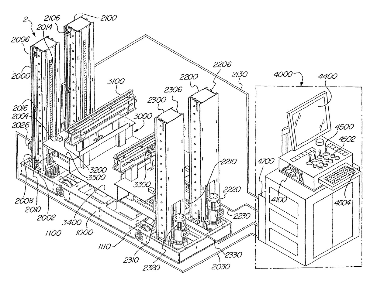
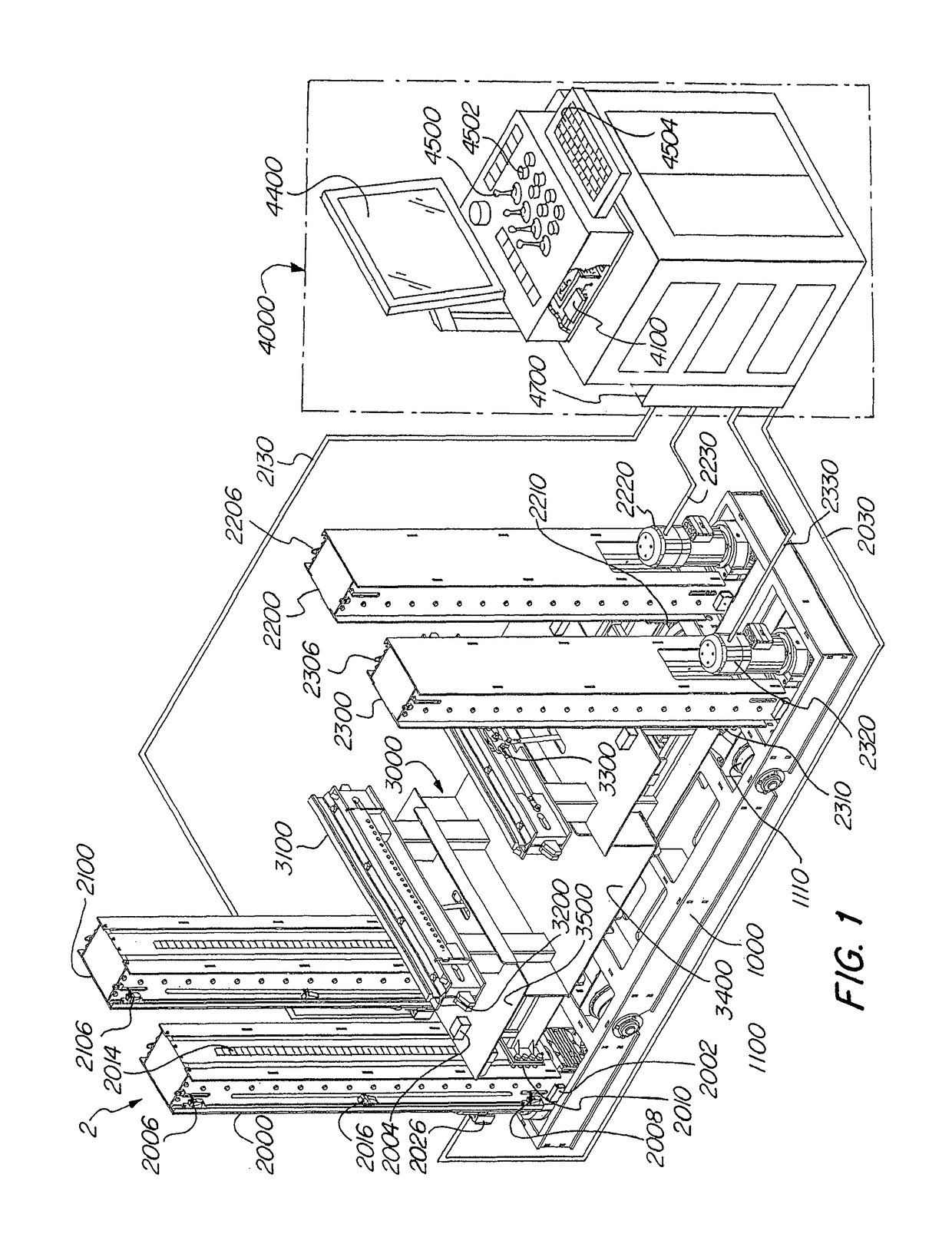
[0045]FIG. 1 shows a lifting and positioning device 2 having four columns 2000,2100,2200,2300. Each column includes a motor 2020,2120,2220,2320 that rotates a screw (not shown) to move a first support 2010,2110,2210,2310 up and down based on signals received from a controller 4000. The columns are affixed to a base 1000 that may have wheels 1100, 1110 to move the positioning apparatus. It is understood that although the wheels are shown as being adapted to run on rails, wheels that move on other surfaces can be provided. One or both sets of wheels 1100, 1110 can be powered, for example by a motor. In addition, where desirable, one or both sets of the wheels can be adapted to turn to steer the positioning apparatus 2. As shown, wires 2030, 2130,2230, 2330 connect the motors to the controller 4000. It is also understood that the wires may be designed to connect to a power source, and the controller could communicate with the individual motors through a wireless connection. Although sh...


PUM


Abstract

Provided is a system and method for positioning a load including an apparatus having a plurality of columns. Each column has a first support and a motor adapted to move the first support along an axis of the column. A second support is connected to at least two of the first supports and a track member for receiving a portion of a vehicle is connected to the second support. Load and position sensors are coupled to the apparatus for transmitting load and position signals. A controller is in communication with the columns and receives the load and position signals to compare the load and position signals to generate at least one control signal that is sent to at least one of said motors for controlling the position of at least one of said first supports.

Description

FIELD OF THE INVENTION[0001]The following invention relates to a lifting and positioning apparatus. More particularly, the following relates to lifting machinery for rail car and engine maintenance.BACKGROUND OF THE INVENTION[0002]In many factories and repair shops, lifting and positioning equipment is used to move heavy objects or to remove parts to expose the underside of the vehicle or to provide easier access for repair and / or replacement of parts and assemblies. This allows a worker to inspect, repair or assemble various items with greater ease than when attempting to work through gaps or crawl spaces.[0003]U.S. Pat. No. 7,603,734 to Connelly et al discloses a system for lifting a passenger boarding bridge for an aircraft that avoids rack fault. The system has two electromechanical screw jacks. Each motor receives a signal for adjusting the height of the tunnel selection and the system uses rotational sensors to monitor the position of the two screw jacks. Connelly does not app...

Claims


Application Information

Patent Timeline
Patent Type & Authority Patents(United States)
IPC IPC(8): B66F7/12B66F7/10B66F11/04B66F7/02B66F11/00
CPCB66F7/025B66F7/10B66F11/00B66F11/04B66F7/02
Inventor KNAPP, RYAN W.MCGONAGLE, PETERO'DONNELL, MARK
Owner MACTON CORP
Why Eureka
Try Eureka