Therapeutic brain cooling system and spinal cord cooling system

a cooling system and brain technology, applied in the field of protective headgear, can solve the problems of insufficient antagonization of long-term lesions, inability to prevent deceleration (i.e., diffuse axonal injury) or other types of projectile injuries, direct brain injuries, etc., and achieve the effect of reducing the temperature of the arterial wall and enhancing the induction of brain cooling

Active Publication Date: 2017-09-26
ROZENTAL RENATO
View PDF90 Cites 2 Cited by
  • Summary
  • Abstract
  • Description
  • Claims
  • Application Information

AI Technical Summary

Benefits of technology

[0014]The present invention relates to a hypothermic helmet for protection of a wearer's brain. The hypothermic helmet has one or more inflatable pads or caps, which may be interconnected, attached inside the helmet body. The system also has at least one canister or container containing different cooling gases, and at least one temperature-sensitive probe capable of determining the wearer's brain temperature, which may be displayed through a color indicative gauge with variable colors or a digital reader, for temperature monitoring. One or more bi-directional pressure-sensitive valves are positioned on the helmet for receiving the canister, which inflates the interconnected pads and cools a wearer's brain in a controlled manner (at a rate of about 0.1° C. to about 0.5° C. / hour) to between about 33° C. and about 36° C. Additionally, an inflatable collar enhances the induction of brain cooling by decreasing the temperature of the arterial blood passing through the neck. One or more bi-directional pressure-sensitive valves are positioned on the collar for receiving the canister filled with cooling gas. A face-mask, visor and thermo-insulating hood may also be attached to the helmet and may be used in conjunction into the collar to create a temperature barrier.
[0015]Another embodiment relates to a hypothermic helmet for protection of a wearer's brain and / or spinal cord. The hypothermic helmet comprises one or more inflatable pads, which may be interconnected. The hypothermic helmet may comprise one or more inflatable spinal cord straps. At least one canister or container containing different cooling gases and at least one temperature-sensitive probe capable of determining temperature for temperature monitoring are also included. The helmet is capable of cooling the user's brain to a mean temperature of about 33° C. to about 36° C. within about 24 hours and is capable of maintaining the temperature of the user's brain within the range for about 24 hours to about 96 hours.
[0016]In another embodiment, this disclosure relates to a brain cooling system and spinal cord cooling system, device or mechanism for use in military helmets, which refer to helmets used in combat. In another embodiment, this disclosure relates to use in non-military helmets, which are helmets used in non-combat scenarios. The brain cooling system comprises an inflatable pad, or a set of interconnected pads, attached to the interior surface of a helmet body, together with a series of valves that allow cooling gases to be delivered from a high pressure canister. The spinal cord cooling system includes one or more, e.g., one, inflatable straps attached to the bottom of the helmet body, together with a series of valves that allow cooling gases to be delivered from a high pressure canister. The brain and spinal systems may be joined at a collar located at a user's neck. The collar further enhances the induction of brain cooling by decreasing the temperature of the arterial blood passing through the neck. The use of different cooling gases permits a controlled lowering (at a rate of about 0.1° C. to about 0.5° C.) of the brain to a temperature to about 33° C., which is about 2.5° C. to 4.5° C. below the core temperature (about 37.5° C.). The brain and spinal cord cooling systems are thermostatically monitored by inclusion of a temperature-sensitive probe, permitting adjustment of the temperature when necessary.
[0017]Maximum pressure inside the system (e.g., the helmet and collar) is controlled by one or more, e.g., three, individual bi-directional pressure-sensitive valves. The availability of the alternative valves avoids the need to move the injured head to implement the cooling mechanism and / or provides optional gas flow rates through the calibration of the individual bi-directional pressure-sensitive valves. Additional features of the system include a visor, face mask and hood which are attached to the helmet body, and which, when combined, create a temperature barrier after the cooling system has been implemented.

Problems solved by technology

The differential movement of the skull and the brain when the head is struck results in direct brain injury, due to diffuse axonal shearing, contusion and brain swelling.
While it provides protection from a diverse range of extraneous insults to the head, it cannot prevent deceleration (i.e., diffuse axonal injury) or other types of projectile injuries (e.g., bullet that perforates the helmet).
Maintaining a constant core temperature, or preventing an increase in temperature, following a variety of brain insults, is not enough to antagonize the development of long-term lesions.
One of the greatest obstacles in moving the application of brain cooling hypothermia from the hospital setting to the field (e.g. war / civilian) has been the availability of adequate cooling techniques.
This method of cooling was unwieldy and required prolonged anesthesia.
No. 2010 / 0211140 all disclose cooling techniques and systems; however, none of these systems are suitable for use in non-hospital settings.
In addition, the system would need to be highly mobile and be incorporated into the user's current equipment, meaning that the system or apparatus would not obstruct the user, impair the functioning of the user's current equipment, or be susceptible to failure resulting from incidental damage prior to activation as could occur in other such systems.

Method used


Image

  • Therapeutic brain cooling system and spinal cord cooling system
  • Therapeutic brain cooling system and spinal cord cooling system
  • Therapeutic brain cooling system and spinal cord cooling system

Examples


Embodiment Construction

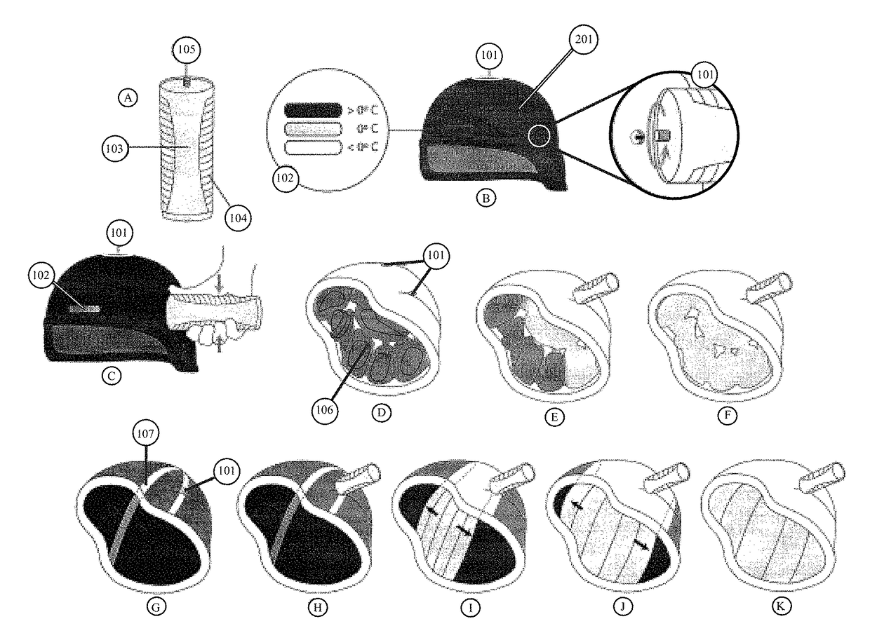
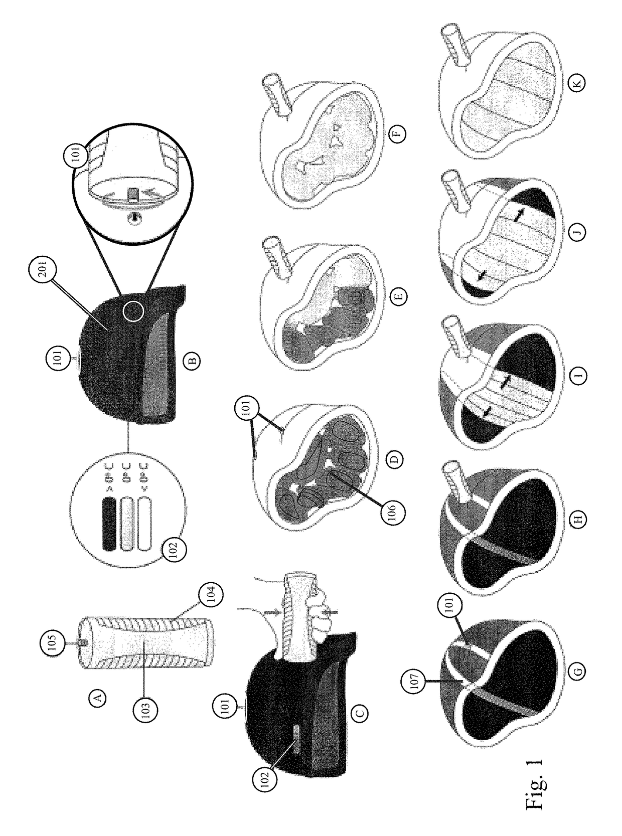
[0032]The present invention relates to a brain cooling system comprising a helmet. In one embodiment, the helmet can be for use in military helmets or in non-military helmets. The brain cooling system comprises an inflatable pad, or a set of inflatable interconnected pads, attached to the interior surface of the helmet body, together with a series of valves that allow coolants, including, but not limited to, pressurized liquids or gases to be delivered from a high pressure canister. The use of different coolants, or cooling gases, achieves (at a rate of about 0.1° C. to about 0.5° C. / hour) mild (about 36° C.) or moderate (about 33° C. to about 35° C.), brain hypothermia, which is about 2.5° C. to about 4.5° C. below the normal range of brain temperature which ranges from about 37.5° C. to about 38.0° C. The brain cooling system is thermostatically monitored by the inclusion of a temperature-sensitive probe and temperature display. The display may be a color indicator gauge, which di...


PUM


Abstract

This disclosure relates to a brain cooling and spinal cord cooling system, device or mechanism for use in military helmets, and in an adapted format in non-military helmets. The system is comprised of an inflatable pad, or a set of interconnected pads, attached to the interior surface of the helmet, together with a series of valves that allow cooling gases to be delivered from a high pressure canister. The use of different cooling gases permits the achievement and maintenance of cooling of the brain for 24 to 96 hours at a mild (36° C.) or moderate (33° C.-35° C.) brain hypothermia, which is 1.5° C.-4.5° C. below the core temperature.

Description

CROSS REFERENCE TO RELATED APPLICATION[0001]This application claims the benefit of U.S. Provisional Application 61 / 359,476, filed Jun. 29, 2010.FIELD OF THE INVENTION[0002]This disclosure pertains to protective headgear (such as a helmet which can act as a brain cooling system and a spinal cord cooling system), device or mechanism to be used in conjunction with helmets in particular to ameliorate the long-term consequences of hypoxic-ischemic or traumatic brain injury and spinal cord injury. The drop in temperature has to be comparatively slow, i.e., less than about 0.5° C. / hr in order to prevent cardiac arrhythmias and maintain blood homeostasis.BACKGROUND[0003]The skull is hard and inflexible, while the brain is soft with the consistency of gelatin. The brain is encased inside the skull. The movement of the skull through space (acceleration) followed by the rapid discontinuation of this action when the skull meets a stationary object (deceleration) causes the brain to move inside ...

Claims


Application Information

Patent Timeline
Patent Type & Authority Patents(United States)
IPC IPC(8): A61F7/00A42B3/10A61F7/10A42B3/12A42B3/28A61F7/02
CPCA61F7/10A42B3/122A42B3/285A61F7/02A61F2007/0008A61F2007/0024A61F2007/0086A61F2007/0092A61F2007/0095A61F2007/0228A61F2007/0233
Inventor ROZENTAL, RENATO
Owner ROZENTAL RENATO
Why Eureka
Try Eureka