Hard-material threaded connection

Active Publication Date: 2017-09-26
CERATIZIT AUSTRIA GES
View PDF44 Cites 4 Cited by
  • Summary
  • Abstract
  • Description
  • Claims
  • Application Information

AI Technical Summary

Benefits of technology

[0007]The object of the present invention is to provide an improved hard-material threaded connection, an improved method for forming a threaded connection between hard material and a component having higher elasticity and an impr

Problems solved by technology

If the difference in the thread pitch is too small, the desired effect is not achieved to a sufficient extent.
On the other hand, if the difference

Method used


Image

  • Hard-material threaded connection
  • Hard-material threaded connection
  • Hard-material threaded connection

Examples


Example

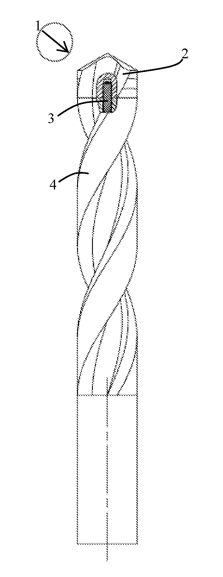
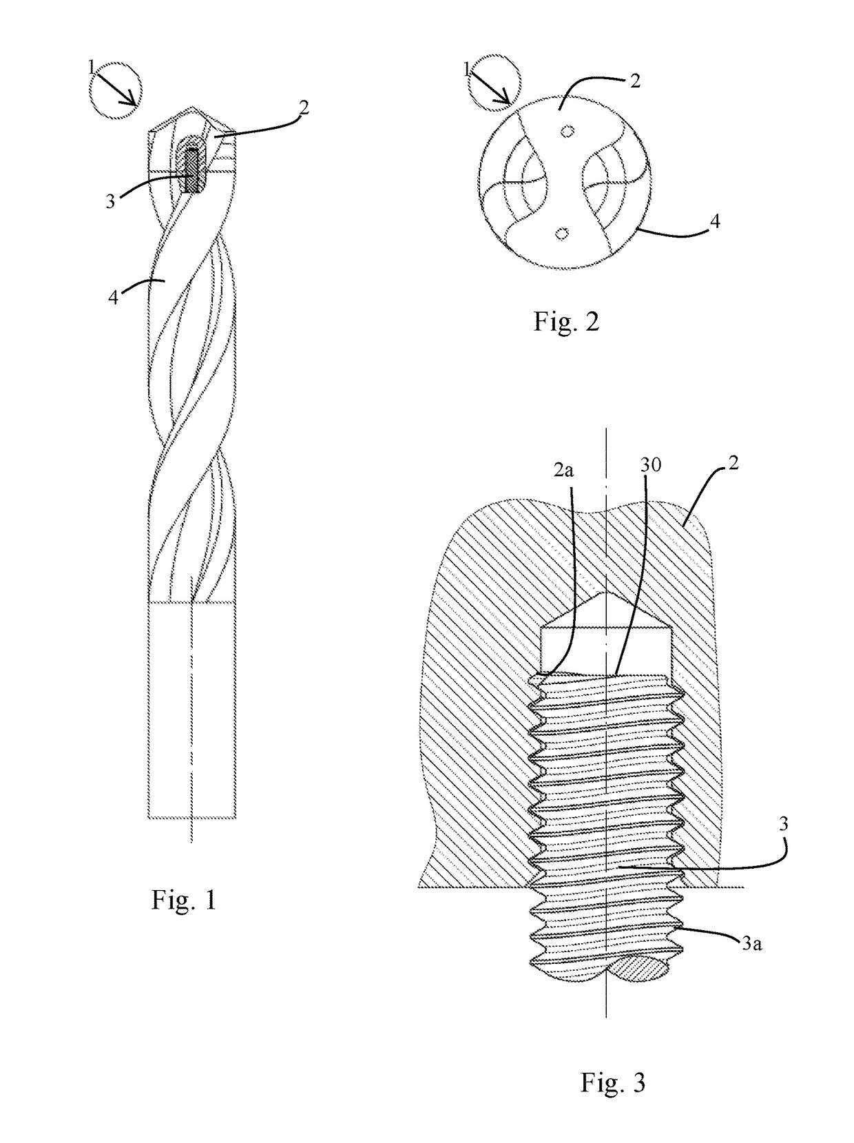
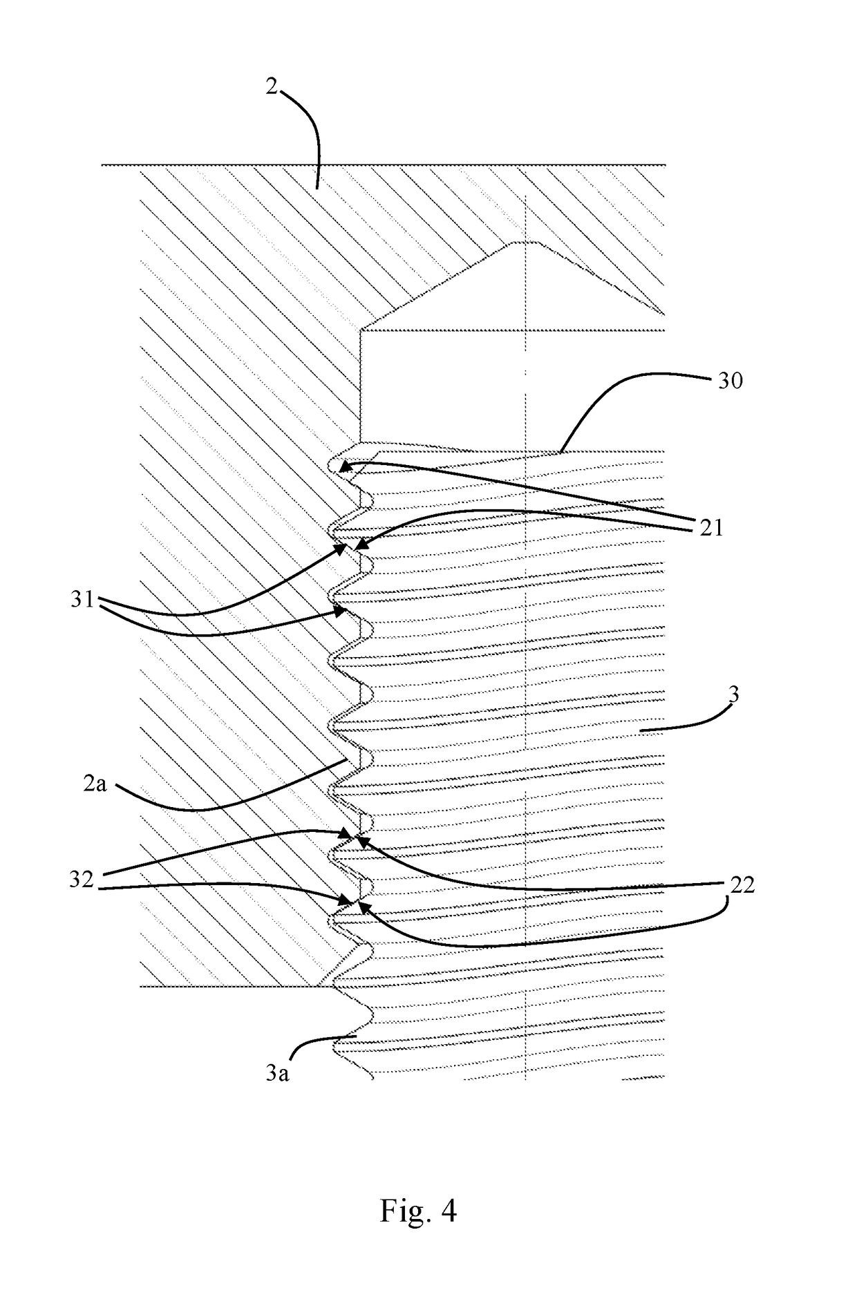
[0033]An embodiment will be described below with reference to FIG. 1 to FIG. 4.

[0034]In the embodiment, the hard-material threaded connection is implemented in a tool 1 with a structural part 2, which has a hard material, and with a component 3 having higher elasticity. The component 3 having higher elasticity may, for example, be manufactured, in particular, from steel. In the embodiment illustrated in the figures, the tool 1 is formed by a drill having an exchangeable cutter made from a hard material. In this case, the structural part 2 which has a hard material is formed by the exchangeable cutter which is designed as a cutting head. In the embodiment illustrated in FIG. 1 to FIG. 4, the component 3 having higher elasticity is formed by a separate threaded body which is connected to a tool body 4. However, it is also possible, for example, that the component having higher elasticity is formed directly by a tool body which is provided with a threaded portion.

[0035]In the exemplary...


PUM

PropertyMeasurementUnit
Fractionaaaaaaaaaa
Fractionaaaaaaaaaa
Fractionaaaaaaaaaa

Abstract

A hard-material threaded connection includes a structural part, which has a hard material and a first threaded portion formed in the hard material, and a component having higher elasticity that has a second threaded portion cooperating with the first threaded portion. The first threaded portion and the second threaded portion have a different thread pitch.

Description

BACKGROUND OF THE INVENTION[0001]Field of the Invention[0002]The present invention relates to a hard-material threaded connection, to a method for forming a threaded connection between hard material and a component having higher elasticity and to a structural part having a hard material and possessing a first threaded portion formed in the hard material.[0003]Particularly in the sector of the cutting machining of metallic workpieces, it is known to use tools which have a tool body and an exchangeable cutter, particularly in the form of a cutting head, fastened to the tool body. The cutter is in this case usually manufactured from a hard material and is designed to come into cutting engagement with the workpiece, whereas the tool body is formed from a material having higher elasticity (as compared with the hard material), such as, for example, from a steel, and connects the cutting head to other components of a machine tool. In this case, the tool body or a threaded body connected to...

Claims


Application Information

Patent Timeline
IPC IPC(8): F16B7/18B23B51/00B23B51/02B23B31/11F16L15/00
CPCB23B51/00B23B31/11B23B51/02F16B7/18B23B2231/0204B23B2231/0244B23B2251/02Y10T29/49826Y10T83/9457Y10T403/68
Inventor SINGER-SCHNOELLER, ALEXANDER
Owner CERATIZIT AUSTRIA GES
Why Eureka
Try Eureka