Hydrogen production apparatus and hydrogen production method

a technology of hydrogen production apparatus and hydrogen production method, which is applied in the direction of energy input, bulk chemical production, separation processes, etc., can solve the problems of large amount of energy and need to apply a large amount of energy

Active Publication Date: 2017-10-03
KOBE STEEL LTD
View PDF11 Cites 2 Cited by
  • Summary
  • Abstract
  • Description
  • Claims
  • Application Information

AI Technical Summary

Benefits of technology

[0010]In this hydrogen production apparatus, the heat collecting device collects at least one among heat of reformed gas, heat of transformed gas, and waste heat from the heating device heating the reformer; the heat supply device supplies heat collected by the heat collecting device to the CO2 separation device; the capturing unit of the CO2 separation device captures CO2 in off-gas after hydrogen separation with the capturing agent; and the heating unit of the CO2 separation device heats the capturing agent after capture by utilizing heat supplied from the heat supply device, in order to cause the capturing agent after capture, which has captured CO2, to release CO2, whereby taking out CO2. Thus, by utilizing at least one among heat of the reformed gas, heat of the transformed gas, and waste heat from the heating device, CO2 can be caused to be released from the capturing agent after capture. This makes it possible to save energy to be additionally applied for causing the capturing agent after capture to release CO2 so that CO2 is taken out. In this hydrogen production apparatus, therefore, energy applied for separation and collection of CO2, which is involved in the hydrogen production, can be reduced.
[0033]As described above, with the hydrogen production apparatus and the hydrogen production method of the present invention, energy applied for separation and collection of CO2, which is involved in the hydrogen production, can be reduced.

Problems solved by technology

This requires to apply a large amount of energy.
In particular, as is the case with JP2002-255510A, in the case where a solid absorbent that can absorb CO2 at a high temperature is used and is caused to absorb CO2 from a reformed gas at a high temperature, it is necessary to heat the solid absorbent to a very high temperature so as to cause the solid absorbent to release CO2, and consequently, it is necessary to apply a very large amount of energy.

Method used


Image

  • Hydrogen production apparatus and hydrogen production method
  • Hydrogen production apparatus and hydrogen production method
  • Hydrogen production apparatus and hydrogen production method

Examples


Embodiment Construction

[0042]Hereinafter, an embodiment of the present invention is described with reference to the drawings.

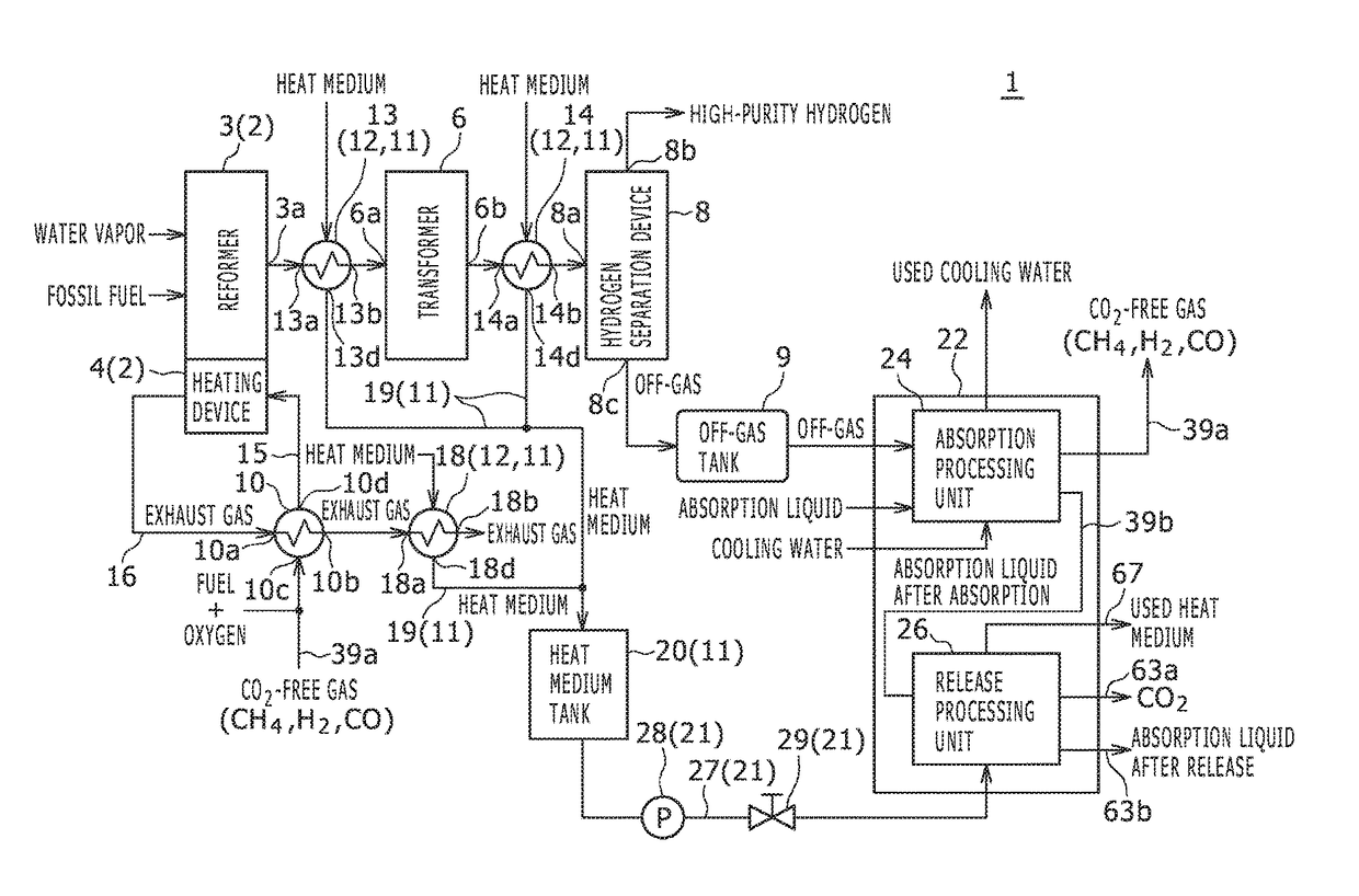
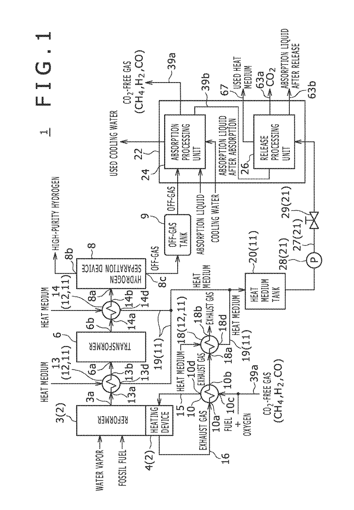
[0043]FIG. 1 illustrates a hydrogen production apparatus 1 according to an embodiment of the present invention. The hydrogen production apparatus 1 is a device for producing hydrogen from fossil fuel such as compressed natural gas (CNG).

[0044]The hydrogen production apparatus 1 includes a reforming device 2, a transformer 6, a hydrogen separation device 8, an off-gas tank 9, an exhaust gas heat exchanger 10, a heat collecting device 11, a heat medium supply device 21, and a CO2 separation device 22, as illustrated in FIG. 1.

[0045]The reforming device 2 reforms fossil fuel such as CNG so as to generate hydrogen-rich reformed gas. The reforming device 2 includes a reformer 3 and a heating device 4.

[0046]To the reformer 3, fossil fuel and water vapor are introduced. The reformer 3 causes a reforming reaction to occur between methane (CH4) in the introduced fossil fuel and the water vap...


PUM

PropertyMeasurementUnit
temperatureaaaaaaaaaa

Abstract

Provided is a hydrogen production apparatus enabling reduction of energy needed for separation and collection of CO2 in the hydrogen production. The hydrogen production apparatus includes a reformer, a heating device heating the reformer, a transformer, a hydrogen separation device separating and taking out hydrogen from transformed gas, a CO2 separation device separating and taking out CO2 from off-gas from which hydrogen was separated by the hydrogen separation device, a heat collecting device collecting heat of the reformed gas, heat of the transformed gas, and waste heat from the heating device, and a heat medium supply device supplying the heat medium having absorbed heat collected by the heat collecting device to the CO2 separation device. The absorption liquid having absorbed CO2 in off-gas is heated by the heat medium heated with collected heat, thereby releasing CO2.

Description

BACKGROUND OF THE INVENTION[0001](Field of the Invention)[0002]The present invention relates to a hydrogen production apparatus and a hydrogen production method.[0003](Description of the Related Art)[0004]Conventionally, a hydrogen production apparatus for producing hydrogen to be supplied to a fuel-cell vehicle or a domestic fuel cell has been proposed. For example, JP2002-255510A discloses an example of such a hydrogen production apparatus.[0005]The hydrogen production apparatus disclosed in JP2002-255510A has the following configuration: raw material gas composed of hydrocarbon gas such as city gas, LP gas, or the like is desulfurized by a desulfurizer, and then, a reforming reaction is caused to occur to the raw material gas and water vapor by a reformer, whereby hydrogen-rich reformed gas is generated; from the reformed gas thus generated, CO2 is removed by a CO2 remover, and then, CO is removed therefrom in a transformation reaction by a CO transformer; thereafter, CO is remov...

Claims


Application Information

Patent Timeline
Patent Type & Authority Patents(United States)
IPC IPC(8): B01J7/00C01B3/48B01D53/14C01B3/38B01D53/18B01J19/24C01B3/50C01B32/50
CPCC01B3/48B01D53/1425B01D53/1475B01D53/18B01J19/24C01B3/38C01B3/508C01B2203/0205C01B2203/0233C01B2203/0283C01B2203/043C01B2203/0415C01B2203/0475C01B2203/08C01B2203/1235C01B2203/142C01B2203/86Y02C10/06Y02P20/129Y02P20/152Y02P20/57Y02P30/30Y02C20/40Y02P20/151Y02P20/50Y02P30/00
Inventor FUJISAWA, AKITOSHIMATSUOKA, AKIRAHANGAI, HIROONOISHIKI, KOJI
Owner KOBE STEEL LTD
Why Eureka
Try Eureka