Synchronizer ring

a technology of synchronizer rings and synchronizers, which is applied in the direction of toothed gearings, belts/chains/gearrings, clutches, etc., can solve the problems of increasing the shifting times, affecting the reliability and precision of lagging radial direction guidance in the cylindrical hollow space in the synchronizer ring hub

Active Publication Date: 2017-10-03
OERLIKON FRICTION SYST GERMANY
View PDF26 Cites 1 Cited by
  • Summary
  • Abstract
  • Description
  • Claims
  • Application Information

AI Technical Summary

Benefits of technology

[0009]It is therefore the object of the invention to provide an improved synchroniser ring which is guided better in the synchronous ring hub and with which no uncontrolled relative movements occur in the operating state between the synchroniser ring and the synchroniser ring hub during and / or outside the synchronisation process.
[0015]This means that a synchroniser ring in accordance with the invention no longer tends to uncontrolled movements, like the conical synchroniser rings known from the prior art, e.g. to small radial excursions or tilt movements which can e.g. be expressed in unpleasant vibrations, due to its conical outer shape which cooperates with a cylindrical inner contact surface in the cylindrical hollow space of the synchroniser ring hub. The reliability and precision of the synchronisation process is thereby considerably positively influenced by use of a synchroniser ring in accordance with the invention, which can contribute to a reduction in the shifting times, which reduces the wear at the friction surface and of the whole synchroniser ring as such and which thus contributes to longer repair and service intervals, quite apart from the fact that the shifting and driving comfort of a motor vehicle is considerably increased by the exceptional guidance of the synchroniser ring in accordance with the invention in the hollow space of the synchroniser ring hub. These positive effects become all the more effective, the more power or torque has to be shifted by a corresponding transmission.

Problems solved by technology

Both synchroniser rings are admittedly basically properly secured by the lobes or abutments against a rotation with respect to the synchroniser ring hub in the operating state, but both lack a reliable guidance in the radial direction in the cylindrical hollow space in the synchronous ring hub.
This means the synchroniser rings known from the prior art are admittedly secured against a rotation in the peripheral direction with respect to the synchronous ring hub, but these rings tend increasedly to uncontrolled movements due to their conical outer shape which cooperates with a cylindrical inner contact surface in the cylindrical hollow space of the synchroniser ring hub, e.g. to small radial excursions or tilt movements which can be expressed e.g. in unpleasant vibrations, and thus have a negative effect on the reliability and precision of the synchronisation process, which can result in an increase in the shifting times, in faster and increased wear of the friction surface and of the total synchroniser ring as such, and thus in shorter repair and service intervals, quite apart from the fact that the shifting and driving comfort of a motor vehicle is considerably restricted by the poor guidance of the synchroniser ring in the hollow space of the synchroniser ring hub and the uncontrolled movements resulting therefrom.

Method used


Image

  • Synchronizer ring
  • Synchronizer ring
  • Synchronizer ring

Examples


Embodiment Construction

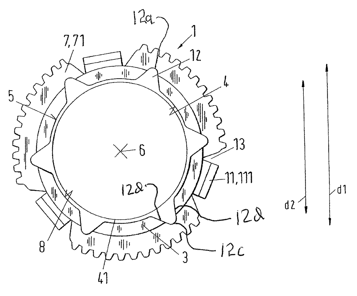
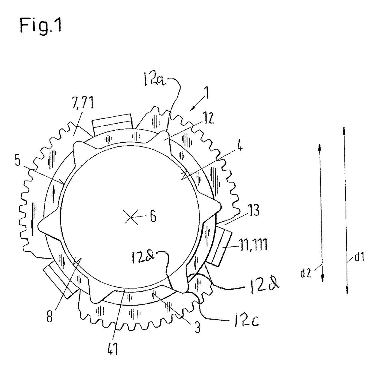
[0039]FIG. 1 shows, in a schematic representation in section, an embodiment of a synchroniser ring in accordance with the invention which is designated as a whole in the following by the reference numeral 1. The same reference numerals in the different Figures designate technically equivalent features or relate to features with a technically equivalent function.

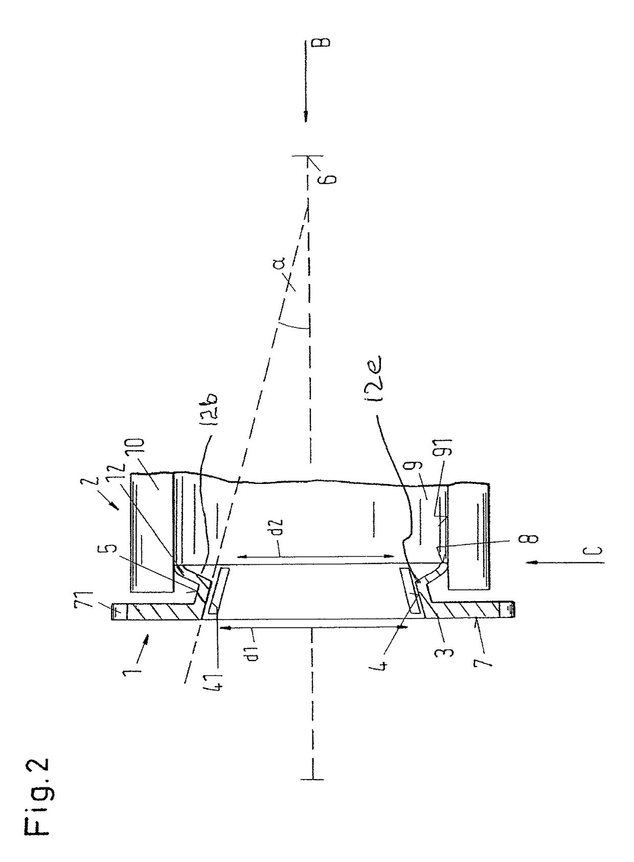
[0040]The synchroniser ring 1 of FIG. 1 includes a conical ring member 3 having an inner friction surface 4 with a carbon friction layer 41 and an outer installation surface 5 which respectively bound the ring member 3 in a radial peripheral direction in a manner known per se. The outer installation surface 5 and the inner friction surface 4 extend substantially parallel to one another at a predeterminable friction angle α, which cannot be seen in FIG. 1, conically around an axial synchroniser ring axis 6 of the synchroniser ring 1.

[0041]The ring member 3 is bounded in the axial direction at a largest conical diameter d 1 by ...


PUM


Abstract

Synchronizer ring made of deep-drawable sheet metal. The ring includes a ring-shaped sheet metal body having a conical section arranged between a wall and a hub surface. One or more radially outwardly projecting guide elements are defined by radially outwardly projecting tapered indentations integrally formed with the ring-shaped sheet metal body. The wall is located at a largest conical diameter side of the ring-shaped sheet metal body and extends substantially perpendicular to a ring body axis. Gear teeth are arranged on a radially outer end of the wall. The one or more guide elements are configured to provide centering guidance relative to a hollow cylindrical surface of a synchronizer ring hub.

Description

CROSS-REFERENCES TO RELATED APPLICATIONS[0001]This application is a continuation of U.S. application Ser. No. 11 / 891,584, filed Aug. 9, 2007, which claims the priority of European Patent Application No. 06120716.3, filed Sep. 15, 2006, the disclosures of which are incorporated herein by reference.BACKGROUND OF THE INVENTION[0002]The invention relates to a synchroniser ring for a synchronising device of a shiftable change speed gear transmission as well as to a manual transmission for a vehicle in accordance with the preamble of the independent claims 1 and 10.[0003]In a mechanical, shiftable change speed gear transmission, e.g. in vehicle transmissions, synchroniser rings serve to synchronize the relative speeds which occur between the gear wheel and the gear shaft on a gear change to one another. The synchronisation is achieved by friction between the corresponding friction partners. The function of such transmissions and the process of the synchronisation procedure are known per s...

Claims


Application Information

Patent Timeline
Patent Type & Authority Patents(United States)
IPC IPC(8): F16D23/02F16H3/38
CPCF16H3/38F16D23/025F16D23/00F16D23/02
Inventor SPRECKELS, MARCUS
Owner OERLIKON FRICTION SYST GERMANY
Why Eureka
Try Eureka