Device for measuring a filling level of a liquid in a container with an ultrasound sensor

a technology of ultrasound sensor and filling level, which is applied in the direction of liquid/fluent solid measurement, instruments, machines/engines, etc., can solve the problem of uninterrupted horizontal slot along the whole height of the inner ring, and achieve the effect of slow flow

Active Publication Date: 2017-10-10
HELLA KG HUECK & CO
View PDF11 Cites 0 Cited by
  • Summary
  • Abstract
  • Description
  • Claims
  • Application Information

AI Technical Summary

Benefits of technology

[0007]With a device for measuring a filling level in a container with an ultrasound sensor, wherein the ultrasound sensor is associated with a damping cup with at least one antechamber, wherein the antechamber comprises at least one outer ring and one inner ring, wherein the inner ring is arranged within the outer ring, provision is made according to the invention for the inner ring and the outer ring to be connected via at least one vertical slot, which extends over at least 50% of the height of the inner ring. In this way a particularly good connection is created between the inner ring and the outer ring allowing a particularly reliable liquid exchange to take place here. Nevertheless, the given structure of the inner and the outer ring will ensure that the dwell time of the oil in the structures of the antechamber is comparatively long thereby allowing the liquid, in particular the oil, to outgas in the antechamber.
[0010]A device of this kind comprises a simple pre-volume structure which increases the degree of efficiency of the device. A particularly good calming and outgassing effect can be achieved for the same size of antechamber. The simple and symmetrical structure without dead volume ensures a very high degree of efficiency. Due to the simple symmetrical construction the venting structure will fit into a very small space.
[0011]Preferably the venting connection and the vent hole are arranged offset by 180°. In this way it is possible to realise a relatively long path of the liquid through the antechamber, and at the same time, to ensure reliable venting.

Problems solved by technology

Preferably however, the vertical slot extends uninterruptedly along the whole height of the inner ring.

Method used


Image

  • Device for measuring a filling level of a liquid in a container with an ultrasound sensor
  • Device for measuring a filling level of a liquid in a container with an ultrasound sensor
  • Device for measuring a filling level of a liquid in a container with an ultrasound sensor

Examples


Embodiment Construction

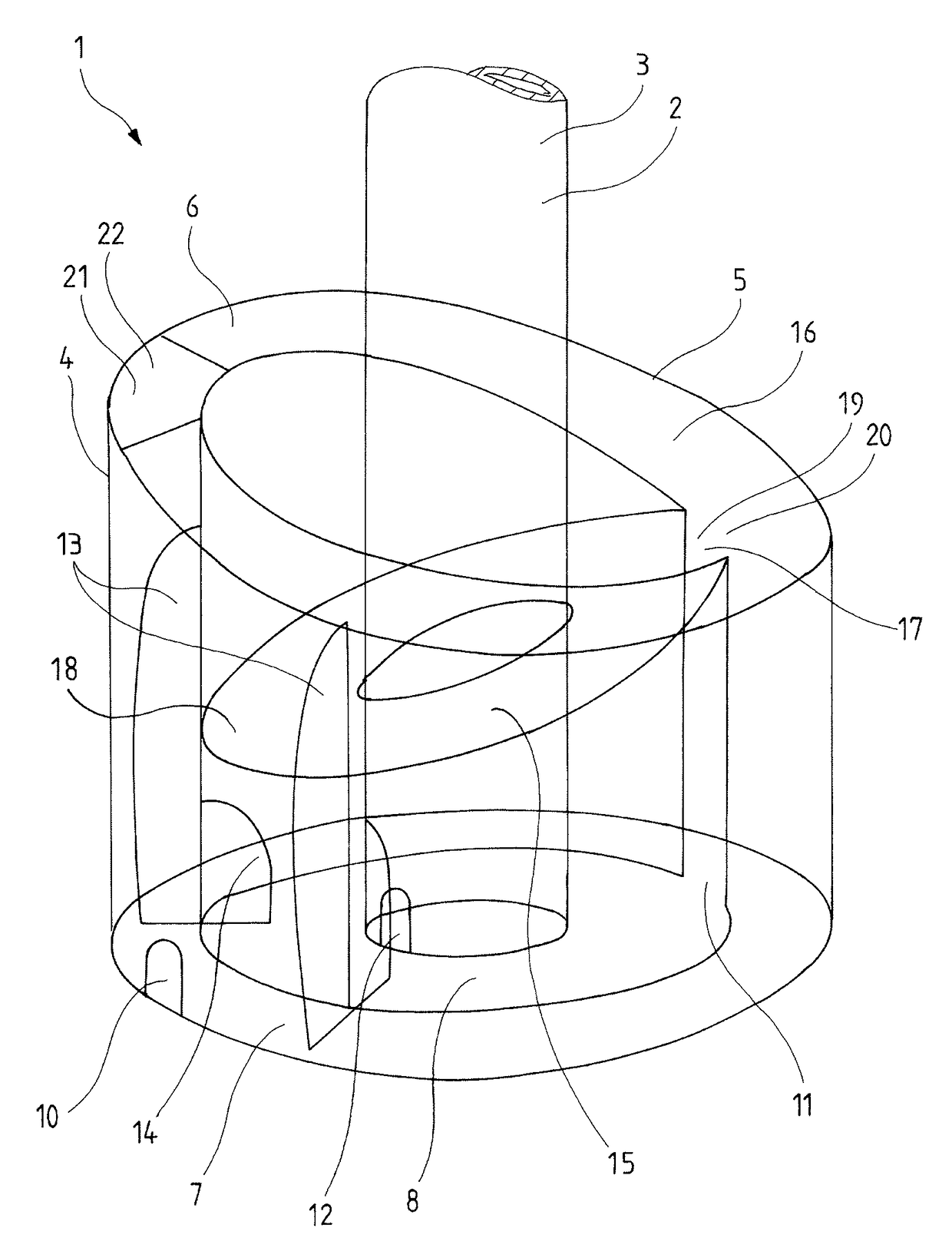
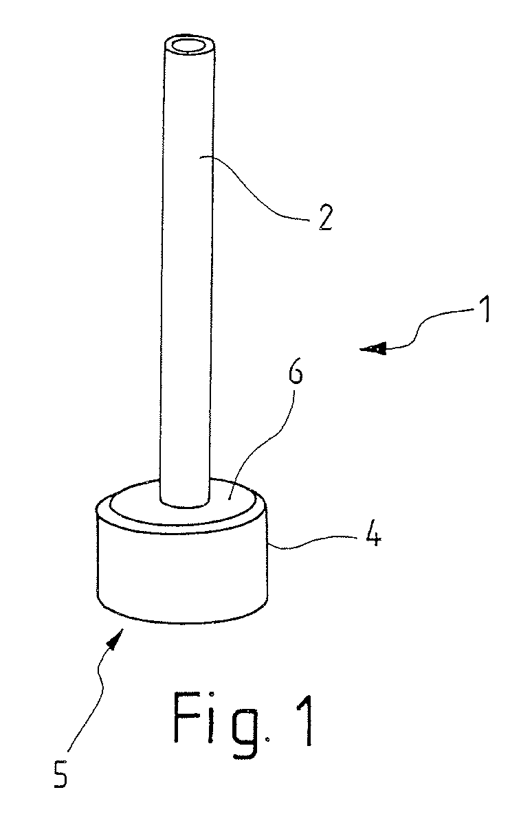
[0027]FIG. 1 shows a damping cup 1 which comprises a pipe 2 in the upper area, through the inside of which a measuring section extends, and which comprises a pre-volume 5 in the lower area. This lower area is essentially composed of an outer wall 4 and a lid 6 and a bottom. At the bottom of the measuring section 3 extending through the pipe 2 an ultrasound sensor is arranged, which emits ultrasound waves, which flow in the measuring section 3 and which are reflected at the boundary surface of the liquid to be measured, in particular oil, with the medium above it, in particular air, and which then flow back to the ultrasound sensor. The filling level can then be calculated based on the travel-time of the signal.

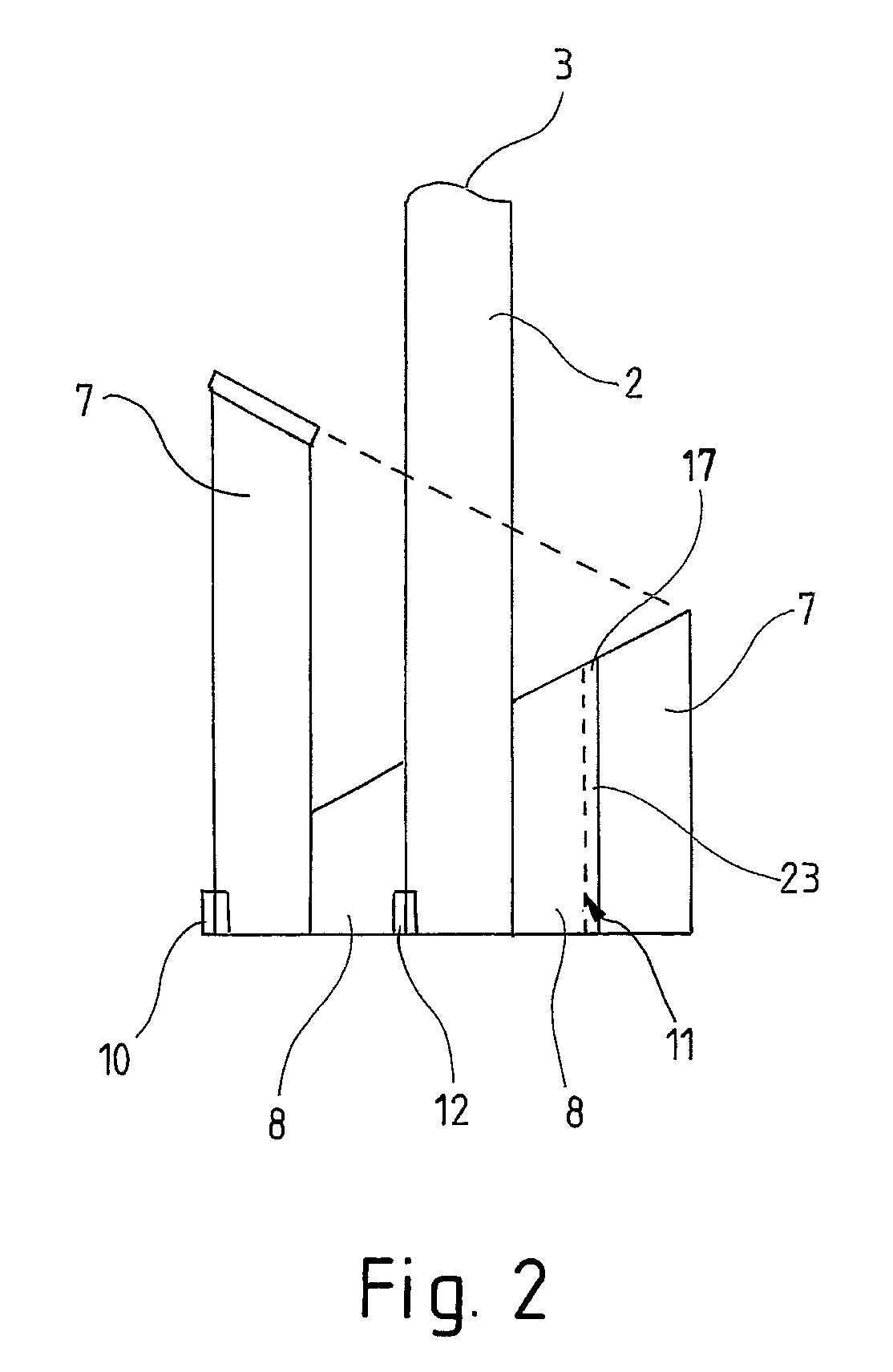
[0028]FIG. 2 represents a cross-section through the damping cup 1. The measuring section 3, at the bottom of which the ultrasound sensor not shown is arranged, extends through the pipe 2. The pre-volume 5 here consists of an inner ring 8 and an outer ring 7. These are formed o...


PUM


Abstract

A device for measuring the filling level of a liquid in a container is provided, which uses an ultrasound sensor. The ultrasound sensor is associated with a damping cup with at least one antechamber, and the antechamber has at least one outer ring and one inner ring. The inner ring is arranged within the outer ring and the ceiling of the inner ring has different heights. The ceiling has a lowest point and a highest point. In the area of the ceiling the inner ring is provided with a venting connection with the outer ring. The venting connection between the inner ring and the outer ring is located at the highest point of the inner ring. The ceiling of the outer ring has different heights including a lowest point and a highest point. A vent hole is provided at the highest point of the outer ring.

Description

BACKGROUND OF THE INVENTION[0001]Field of the Invention[0002]The invention relates to a device for measuring a filling level of a liquid in a container with an ultrasound sensor, wherein the ultrasound sensor is associated with a damping cup with at least one antechamber, wherein the antechamber comprises at least one outer ring and one inner ring, wherein the inner ring is arranged within the outer ring.[0003]Brief Summary of the Related Art[0004]A generic device for measuring a filling level of a liquid in a container is known from the WO 2008 / 009277 A1. The container concerned is, in particular, a container for holding engine oil. The oil level in engines is ascertained using ultrasound sensors. These emit sound waves, which reflect at the boundary surface between two media, in this case between gas and oil, and are then received back by the ultrasound sensor. The filling level in the container in which the liquid is present can be ascertained from the recorded travel-time of the...

Claims


Application Information

Patent Timeline
Patent Type & Authority Patents(United States)
IPC IPC(8): G01F23/296
CPCG01F23/2962G01F23/2968G01F23/296
Inventor STRACKERJAN, FALKOTONEWIZKI, SERGEJZOYKE, INGO
Owner HELLA KG HUECK & CO
Why Eureka
Try Eureka