Supercharge Your Innovation With Domain-Expert AI Agents!

Rotor of an electrical machine and electrical machine

a technology of electrical machines and rotors, applied in the direction of dynamo-electric machines, magnetic circuit rotating parts, magnetic circuit shapes/forms/construction, etc., can solve problems such as component failur

Active Publication Date: 2017-10-10
MERITOR ELECTRIC VEHICLES GERMANY GMBH +2
View PDF19 Cites 0 Cited by
  • Summary
  • Abstract
  • Description
  • Claims
  • Application Information

AI Technical Summary

Benefits of technology

The technical effect of this patent is to improve the performance of a rotor with a fan in an electrical machine.

Problems solved by technology

In particular, in fans made of thin sheet metal these centrifugal forces result in a bending moment at the fastening points of the fan blades on the fan support ring (supporting element) so that in certain circumstances permissible mechanical tensions may be exceeded in these areas during normal operation of the electrical machine, possibly resulting in component failure.

Method used


Image

  • Rotor of an electrical machine and electrical machine
  • Rotor of an electrical machine and electrical machine
  • Rotor of an electrical machine and electrical machine

Examples


Embodiment Construction

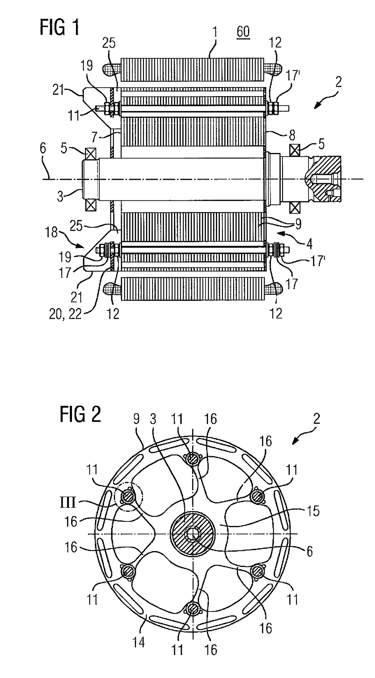
[0040]The diagram according to FIG. 1 shows an electrical machine 60 with a stator 1 and a rotor 2. The rotor 2 has a rotor shaft 3 and a laminated rotor core 4. The rotor shaft 3 is mounted in bearings 5 so that the rotor shaft 3, and with it the entire rotor 2, can be rotated around a rotational axis 6 of the electrical machine.

[0041]Insofar as the terms “axial”, “radial” and “tangential” are used, they relate to the rotational axis 6. The term “axial” means a direction parallel to the rotational axis 6. The term “radial” means a direction orthogonal to the rotational axis 6 towards or away from the rotational axis 6. The term “tangential” means a direction orthogonal to the rotational axis 6 and orthogonal to the radial direction, in other words, at a constant radial distance from the rotational axis 6 in a circle around the rotational axis 6.

[0042]As a rule, in accordance with the diagram of FIG. 1 the rotor 2 is arranged radially inside the stator 1. The electrical machine is t...


PUM


Abstract

A rotor (2) of an electrical machine (60) has a laminated rotor core (4). A fan (18), which is arranged at the end face in the laminated rotor core (4) is provided for cooling purposes. The fan has a fan blade (21) and a supporting element (20) for the fan blade (21), wherein the fan blade (21) extends by way of a first section (31) beyond the supporting element (20) in a first axial direction and extends by way of a second section (33) beyond the supporting element (20) in a second axial direction (34) which is opposite the first axial direction (32).

Description

CROSS-REFERENCES TO RELATED APPLICATIONS[0001]This application is the U.S. National Stage of International Application No. PCT / EP2013 / 065612, filed Jul. 24, 2013, which designated the United States and has been published as International Publication No. WO 2014 / 032868 and which claims the priority of German Patent Application, Serial No. 102012215503.1, filed Aug. 31, 2012, pursuant to 35 U.S.C. 119(a)-(d).BACKGROUND OF THE INVENTION[0002]The present invention relates to a rotor of an electrical machine.[0003]The rotor may have a laminated rotor core which is connected to a rotor shaft of the rotor in a torque-proof manner, wherein the laminated rotor core extends from a first axial end face of the laminated rotor core to a second axial end face of the laminated rotor core viewed in the direction of a rotational axis of the laminated rotor core.[0004]Furthermore, the present invention relates to an electrical machine, the electrical machine having a stator and a rotor, the rotor bei...

Claims


Application Information

Patent Timeline
Patent Type & Authority Patents(United States)
IPC IPC(8): H02K1/32H02K1/27H02K9/04H02K9/06
CPCH02K9/04H02K1/32H02K1/276H02K9/06
Inventor WETZEL, WOLFGANG
Owner MERITOR ELECTRIC VEHICLES GERMANY GMBH
Features
  • R&D
  • Intellectual Property
  • Life Sciences
  • Materials
  • Tech Scout
  • Unparalleled Data Quality
  • Higher Quality Content
  • 60% Fewer Hallucinations
Learn More