
Sensor and valve integrated into a patient interface

a sensor and valve technology, applied in the field of airway pressure support systems, can solve the problems of sleep apnea sufferers at risk for excessive mortality, possible severe degrees of oxyhemoglobin desaturation, and sleep fragmentation

Inactive Publication Date: 2017-10-17
KONINK PHILIPS ELECTRONICS NV
View PDF11 Cites 4 Cited by
  • Summary
  • Abstract
  • Description
  • Claims
  • Application Information

AI Technical Summary

Benefits of technology

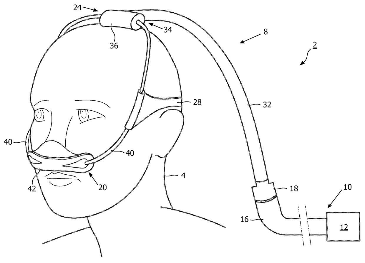
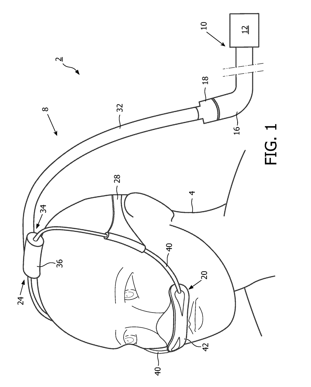
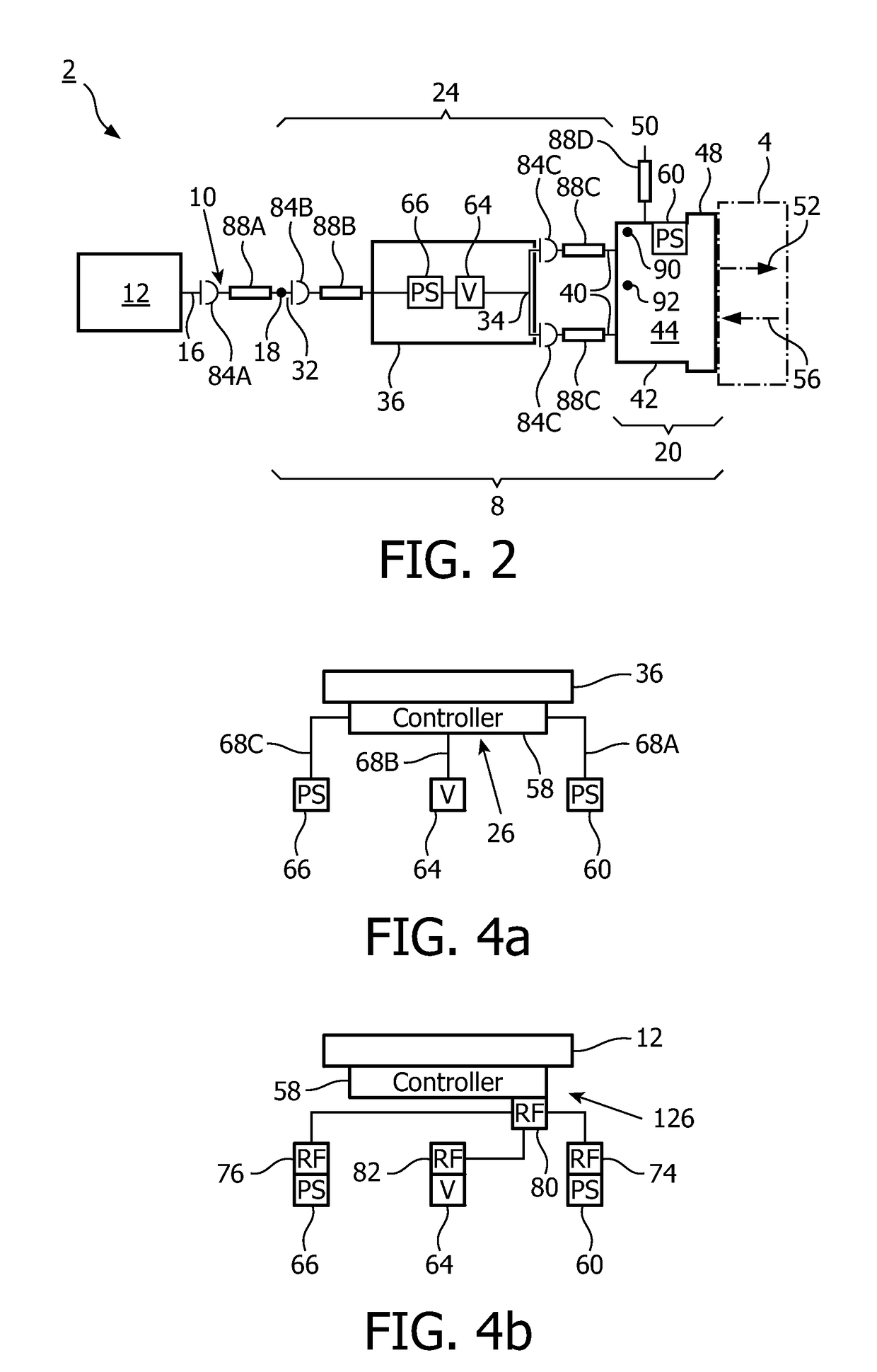
This configuration minimizes the time delay between condition detection and therapeutic pressure adjustment, enabling the use of flexible and unconventional mask designs while improving therapeutic efficacy and patient comfort.

Problems solved by technology

Those afflicted with sleep apnea experience sleep fragmentation and complete or nearly complete cessation of ventilation intermittently during sleep with potentially severe degrees of oxyhemoglobin desaturation.
Sleep apnea sufferers may be at risk for excessive mortality from these factors as well as by an elevated risk for accidents while driving and / or operating potentially dangerous equipment.
Even if a patient does not suffer from a complete or nearly complete obstruction of the airway, it is also known that adverse effects, such as arousals from sleep, can occur where there is only a partial obstruction of the airway.
Partial obstruction of the airway typically results in shallow breathing referred to as a hypopnea.
It is also known, however, that known pressure support systems have certain shortcomings associated with delays in the detection of breathing conditions and additional delays in therapeutically altering the pressure support in response to the breathing conditions.
This delay is further increased by the system dynamics of the mechanism used to adjust the pressure.
This assumption in the algorithms severely limits airflow circuit designs to standard structures with relatively large cross sectional areas that provide generally constant and consistent levels of airflow resistance and compliance.
These features, however, will (by definition) have high resistance to airflow, and the resistance levels could change significantly throughout the course of the night (i.e. they are not constant and consistent).
In addition, soft materials could have relatively high mechanical deformation which would lead to significant and variable volumetric compliance in the airflow circuit.

Method used


Image

  • Sensor and valve integrated into a patient interface
  • Sensor and valve integrated into a patient interface
  • Sensor and valve integrated into a patient interface

Examples


Embodiment Construction

[0035]As used herein, the singular form of “a”, “an”, and “the” include plural references unless the context clearly dictates otherwise. As used herein, the statement that two or more parts or components are “coupled” shall mean that the parts are joined or operate together either directly or indirectly, i.e., through one or more intermediate parts or components, so long as a link occurs. As used herein, “directly coupled” means that two elements are directly in contact with each other. As used herein, “fixedly coupled” or “fixed” means that two components are coupled so as to move as one while maintaining a constant orientation relative to each other.

[0036]As used herein, the word “unitary” means a component is created as a single piece or unit. That is, a component that includes pieces that are created separately and then coupled together as a unit is not a “unitary” component or body. As employed herein, the statement that two or more parts or components “engage” one another shal...


PUM


Abstract

An improved patient interface assembly and pressure support system integrate a pressure sensor and a valve into the patient interface assembly and employs closed loop control between the sensor and the valve in order to limit delay between the time at which a condition indicative of abnormal breathing or flow load during normal breathing is experienced by a patient and the time at which altered pressure support is received by the patient.

Description

CROSS-REFERENCE TO RELATED APPLICATIONS[0001]This patent application claims the priority benefit under 35 U.S.C. §371 of international patent application no. PCT / IB2012 / 052361, filed May 11, 2012, which claims the priority benefit under 35 U.S. C. §119(e) of U.S. Provisional Application No. 61 / 485,789 filed on May 13, 2011, the content of which are herein incorporated by reference.BACKGROUND OF THE INVENTION[0002]1. Field of the Invention[0003]The present invention relates to airway pressure support systems and, more particularly, to a patient interface assembly for a pressure support system in which a pressure sensor and a valve of a flow control circuit are integrated into the patient interface assembly.[0004]2. Description of the Related Art[0005]Many individuals suffer from disordered breathing during sleep. Sleep apnea is a common example of such sleep disordered breathing suffered by millions of people throughout the world. One type of sleep apnea is obstructive sleep apnea (O...

Claims


Application Information

Patent Timeline
Patent Type & Authority Patents(United States)
IPC IPC(8): A61M16/20A61M16/06A61M16/00A61M16/08
CPCA61M16/20A61M16/0051A61M16/06A61M16/203A61M16/0683A61M16/0825A61M2016/0027A61M2205/3331A61M2205/3561A61M2205/3592A61M16/026
Inventor LUCCI, CHRISTOPHER SCOTTLOCKHART, HAROL ALLENSMITH, IV, DAVID W.O'CONNOR, NATHAN FRANCISGRASHOW, JONATHAN SAYER
Owner KONINK PHILIPS ELECTRONICS NV
Learn More