Compound power mechanism and electric bicycle

a power mechanism and electric bicycle technology, applied in the direction of dynamo-electric machines, dynamo-electric components, vehicle components, etc., can solve the problems of complex structure, easy water flow, and bicycle off-balance, so as to improve the route and the power of electric bicycles, reduce the size of the motor, and improve the manufacturing cost of the motor

Inactive Publication Date: 2017-10-17
WU SHYANG JUN
View PDF25 Cites 5 Cited by
  • Summary
  • Abstract
  • Description
  • Claims
  • Application Information

AI Technical Summary

Benefits of technology

[0005]The primary object of the present invention is to provide a compound power mechanism and an electric bicycle, enabling motor power and pedal power to be integrated into a power mechanism. The bicycle can be driven by the motor power or the pedal power. The size is reduced and the cost of manufacture is lowered.
[0008]The structure and effects of the compound power mechanism and the electric bicycle of the present invention are described hereinafter. The motor drive shaft is a hollow shaft. The crank drive shaft is inserted in the motor drive shaft to be integrated into a single shaft structure so as to reduce the size of the motor. The single shaft structure can be coupled with freewheels respectively. The freewheels are further coupled to the drive sprocket. The motor drive shaft and the crank drive shaft can turn the one-section or multi-section derailleur at the rear of the bicycle, respectively. They don't interfere with each other. Both the motor power and the pedal power can be applied, enhancing the route and the power of the electric bicycle. The freewheels and the drive sprocket are normal parts of the existing bicycle. There is no need to manufacture specially. The forging structures are just assembled, so the manufacturing cost of the motor is lowered accordingly. The motor is a low-speed multi-pole brushless motor, which is small in size and has high efficiency compared to the brushed motor.

Problems solved by technology

However, the hub motor has the problems that the hub motor makes the bicycle off-balance and that water can easily flow into the hub motor.
The problem of the brushless motor applications is how to couple with pedal cranks for the electric bicycle to provide both motor power and pedal power without making the structure too complicated.

Method used


Image

  • Compound power mechanism and electric bicycle
  • Compound power mechanism and electric bicycle
  • Compound power mechanism and electric bicycle

Examples


Embodiment Construction

[0016]Embodiments of the present invention will now be described, by way of example only, with reference to the accompanying drawings.

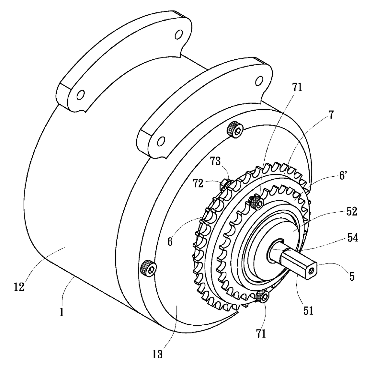
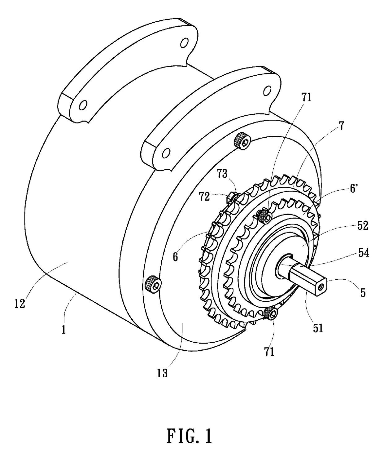
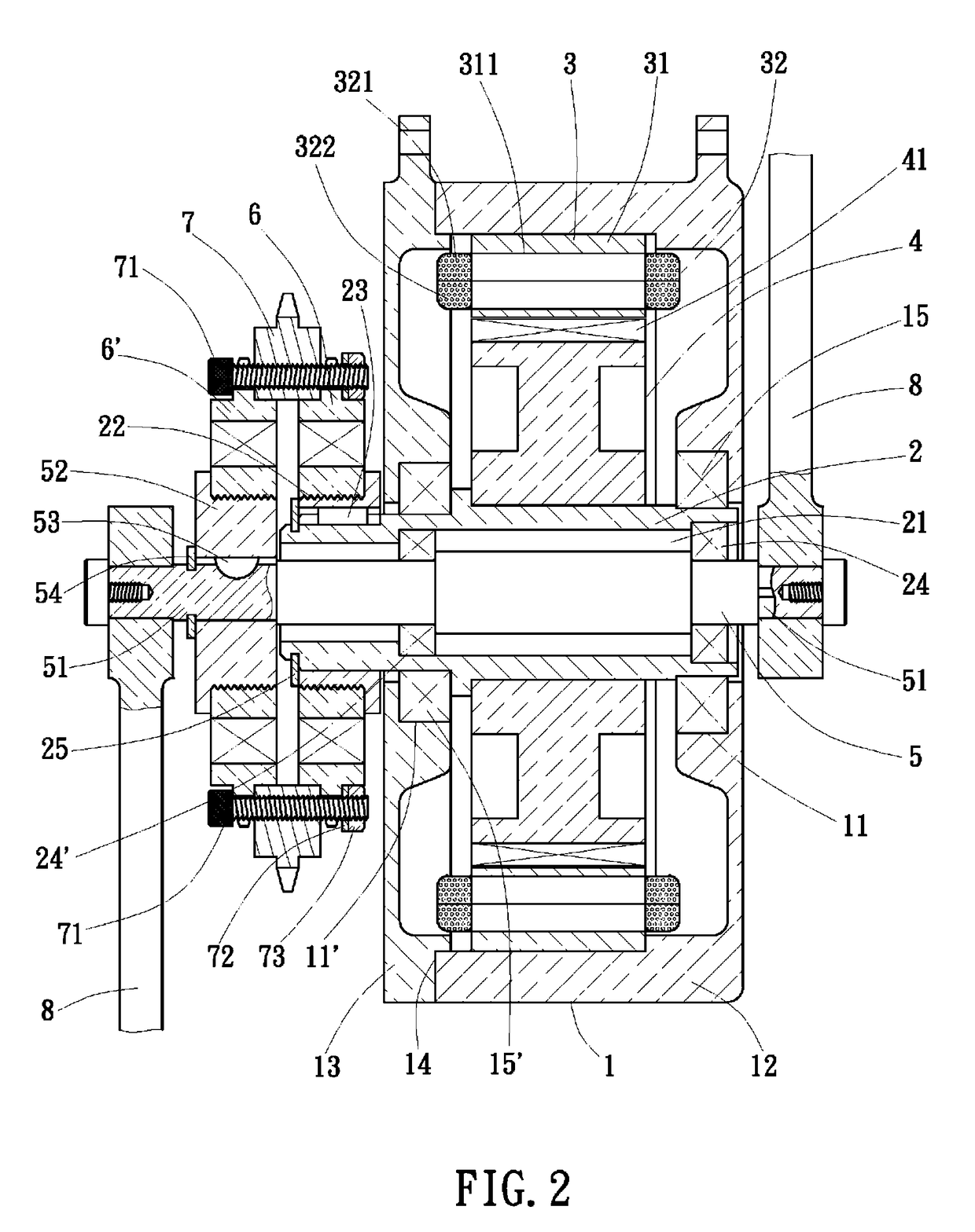
[0017]As shown in FIG. 1 and FIG. 2, the present invention discloses a compound power mechanism mounted to an electric bicycle, enabling the electric bicycle to provide both motor power and pedal power. In a preferred embodiment, the present invention comprises a motor casing 1, a motor drive shaft 2, a stator 3, a rotor 4, a crank drive shaft 5, two freewheels 6, 6′, and a drive sprocket 7.

[0018]The motor casing 1 is fixed to a frame 101 (as shown in FIG. 6 or FIG. 7) of a bicycle 10. The motor casing 1 can be a closed hollow casing. Two sides of the motor casing 1 are provided with shaft holes 11, 11′; As shown in FIG. 2 and FIG. 4, the motor casing 1 comprises a main casing 12 and a side cover 13 coupled to the main casing 12. One side of the main casing 12 is provided with the shaft hole 11, and another side of the main casing 12 is provided with ...


PUM


Abstract

A compound power mechanism and an electric bicycle are provided. The compound power mechanism includes a motor casing fixed to the bicycle, a motor drive shaft coupled with a rotor, and a stator provided in the motor casing. A crank drive shaft is disposed in the motor drive shaft. Two ends of the crank drive shaft extend out of the two ends of the motor drive shaft and are coupled with pedal cranks. A freewheel is coupled to a respective end of the motor drive shaft and the crank drive shaft. A drive sprocket is located between and coupled to the two freewheels and adapted to bring a bicycle chain to turn. The drive sprocket can be driven by the motor drive shaft or by the crank drive shaft when pedaled. The size of the motor is reduced and the cost of manufacture is lowered.

Description

BACKGROUND OF THE INVENTION[0001](a) Field of the Invention[0002]The present invention relates to a compound power mechanism and an electric bicycle, and more particularly to a compound power mechanism able to integrate brushless motor power with pedal power.[0003](b) Description of the Prior Art[0004]These days, an electric bicycle is provided with a brushless motor instead of a brushed motor. The brushless motor is small in size and has high efficiency, and provides a multi-pole (10 to 32 poles) and low speed. During the development of electric bicycles, a hub motor is derived, such as disclosed in U.S. Pat. No. 3,921,741, U.S. Pat. No. 7,628,518, and U.S. Pat. No. 5,828,145. The hub motor is directly mounted on the front wheel or the rear wheel of a bicycle, without transmission of a chain. However, the hub motor has the problems that the hub motor makes the bicycle off-balance and that water can easily flow into the hub motor. Thus, the motor should be disposed at the center of ...

Claims


Application Information

Patent Timeline
Patent Type & Authority Patents(United States)
IPC IPC(8): B62M6/55H02K7/116H02K7/14B62M23/00B62M6/70
CPCB62M6/55B62M6/70B62M23/00H02K7/116H02K7/14
Inventor WU, SHYANG-JUN
Owner WU SHYANG JUN
Why Eureka
Try Eureka