Mutually calibrated magnetic imaging array

a magnetic imaging array and mutual calibration technology, applied in the field of magnetic imaging arrays, can solve the problems of tedious phantom-type approach, and achieve the effects of less cumbersome operation, convenient and fast array operation, and convenient transportation

Active Publication Date: 2017-10-17
QUSPIN
View PDF20 Cites 42 Cited by
  • Summary
  • Abstract
  • Description
  • Claims
  • Application Information

AI Technical Summary

Benefits of technology

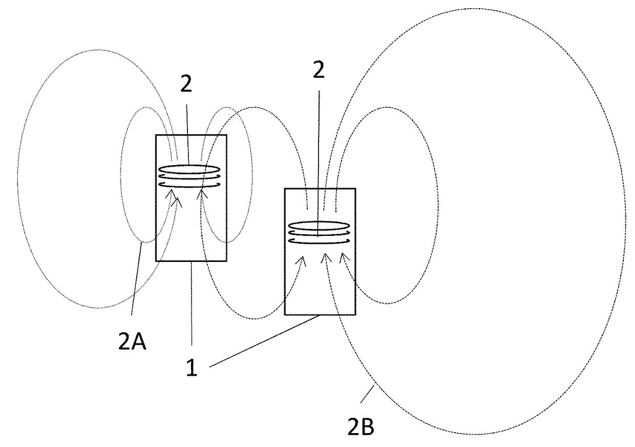
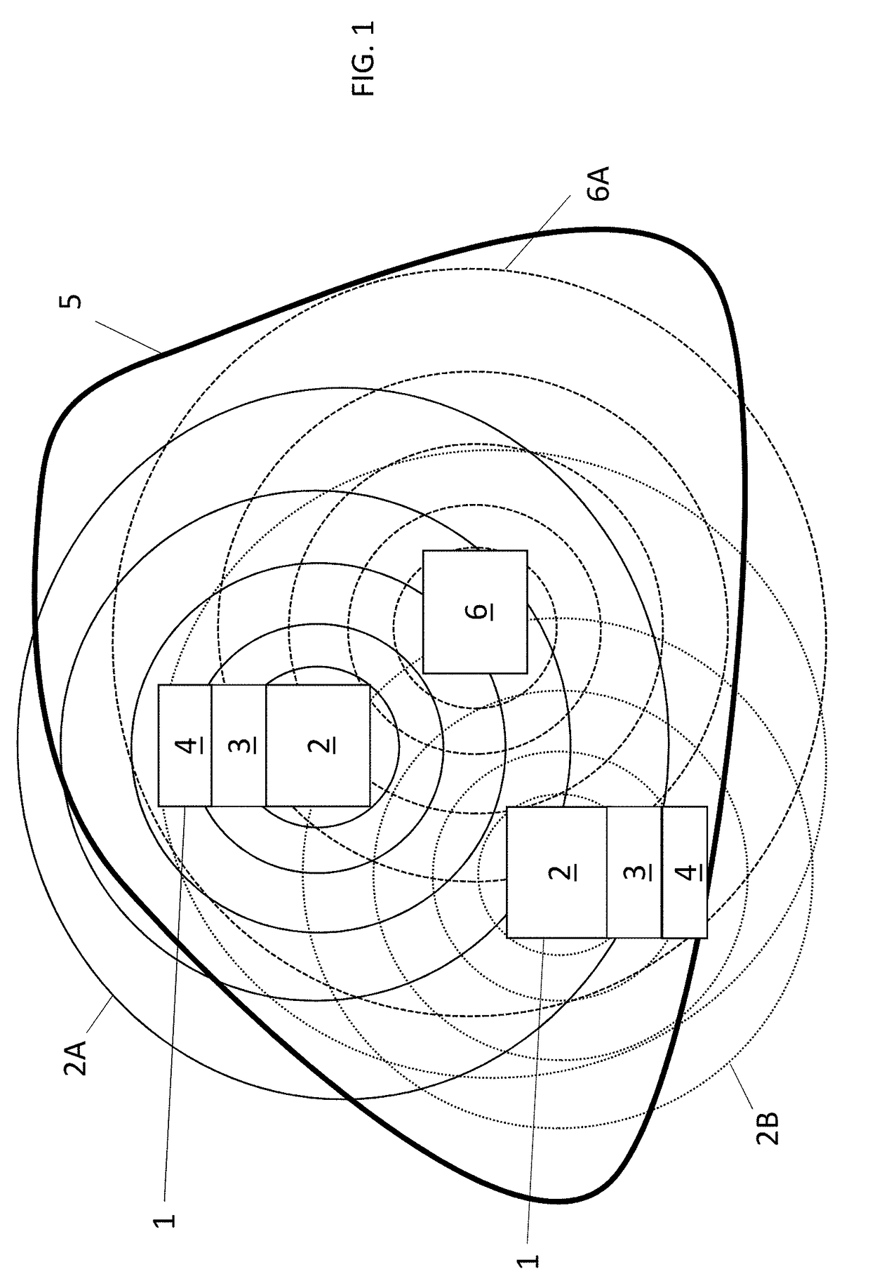
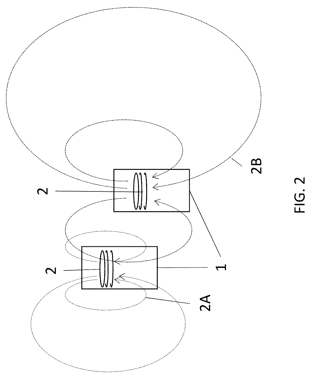
[0010]The present invention is a system wherein at least one non-target magnetic field source is integrally connected to a magnetic sensor, or magnetometers, i.e., are one piece. The orientation and location of the source with respect to the magnetometer is known, but the location of the source with respect to the other non-target sources in the array is not. This is a major difference to calibration with a phantom. Further, the system comprises a computation unit to calculate parameters...

Problems solved by technology

These parameters require more frequent calibration for every measurement i...

Method used


Image

  • Mutually calibrated magnetic imaging array
  • Mutually calibrated magnetic imaging array
  • Mutually calibrated magnetic imaging array

Examples


example 1

[0025]As an example, a simple magnetic imaging array made up of magnetic array devices 40, as described above, has been constructed out of two optically-pumped magnetometers (OPMs) 32, magnetic coils 31A, 31B, and 31C, and a computation unit 33, as shown in FIG. 4. Each OPM 32 measured the field in two nearly orthogonal directions. A schematic diagram of the imaging array is shown in FIG. 4. Three coils 31A, 31B, and 31C, were wrapped around each of the OPM magnetometers 32 in nearly orthogonal directions serving as three non-target sources. The relative positions and orientations of each coil with respect to the OPM magnetometer 32 it is attached to are measured carefully. In this way, the magnetic field of each of the dipolar sources was known relative to the magnetometer itself. Oscillating non-target magnetic fields were applied to the six dipoles at frequencies of 80 Hz, 81 Hz, 83 Hz, 84 Hz, 86 Hz, and 87 Hz, respectively. The fields were recorded continuously in each of the fo...


PUM


Abstract

A mutually calibrated magnetic imaging array system is described. The system includes a non-target magnetic source rigidly attached to a magnetometer, and an attached control unit to measure and adjust several parameters of a magnetic imaging array. A non-target magnetic field source is used to generate a well-defined and distinguishable spatial magnetic field distribution. The source is rigidly attached directly to a magnetometer, while the relative positions of the magnetometers are unknown. The magnetic imaging array is used to measure the strength of the non-target source magnetic fields and the information is used to calibrate several parameters of the array, such as, but not limited to, effective magnetometer positions and orientations with respect to each other and cross-talk between the magnetometers. The system, and method described herein eliminates the need for a separate calibration phantom.

Description

[0001]The following application is an application for patent under 35 USC 111 (a). This invention was made with government support under HD074495 awarded by the National Institutes of Health. The government has certain rights in the inventionFIELD OF INVENTION[0002]This disclosure relates to the field of magnetic imaging arrays, specifically a device used to create an array, and method thereof.BACKGROUND[0003]Optically pumped magnetometers (OPMs), also called atomic magnetometers, optical magnetometers, or optical atomic magnetometers, are used in a number of scientific and advanced technology applications including medical imaging. In their simplest form, they contain a light source, a container to hold atoms, and a detector. The light source may be a laser or other optical device used to produce light of a certain wavelength. The container may be a vapor cell or other device used to house atoms. The detector would necessarily be specific to the light output.[0004]Single OPMs or sm...

Claims


Application Information

Patent Timeline
IPC IPC(8): G01V3/00A61B5/04G01R35/00G01R33/032
CPCG01R35/005G01R33/032A61B5/04008A61B2560/0223A61B2562/0223G01R33/26A61B5/245
Inventor ALEM, ORANGSHAH, VISHALKNAPPE, SVENJA
Owner QUSPIN
Why Eureka
Try Eureka