Surgical device employing a cantilevered beam dissector

a technology of cantilever beam and dissector, which is applied in the field of surgical instruments, can solve the problems of significant distal end movement, and achieve the effect of more transportability

Active Publication Date: 2015-09-17
RONTAL MICHAEL DR
View PDF18 Cites 12 Cited by
  • Summary
  • Abstract
  • Description
  • Claims
  • Application Information

AI Technical Summary

Benefits of technology

[0038]In the brief intervals between these two modes a fast sensor can look for dampening of the tip motion. A feedback to the microprocessor which controls the signal generator can compensate for the dampening. Again the feedback is continuous so seamless monitoring and control is achieved.
[0039]The electrical power for this device in one preferred embodiment is a DC current provided by a battery, however a medical grade isolation transformer and power supply will also work. This current is controlled by a MOSFET to produce a square wave signal in the primary of a transformer. The voltage is stepped up in the secondary to hundreds of volts. The square wave leaving the secondary passes through a capacitor and a diode forming a clamping circuit. A sine or triangular wave is formed and drives the MFC such that they are forward biased in the Fz mode. This is important as the MFCs typically can be driven to +1,500 volts in the forward biased mode, but only 500 volts in the reversed biased mode. Important for this device is the low voltage (battery) source for the transformer. Besides making the device more transportable it is safer than a conventional wall source and obviates concerns of a ground fault and possible electrocution of the patient or surgeon.

Problems solved by technology

Thirdly, the flat beam is cantilevered from a relatively massive blocking mass made of a highly rigid and dense material.
The most deflection in the My mode is at the resonate frequency, however harmonics of the My resonate frequency will also cause significant distal end movement.

Method used


Image

  • Surgical device employing a cantilevered beam dissector
  • Surgical device employing a cantilevered beam dissector
  • Surgical device employing a cantilevered beam dissector

Examples


Embodiment Construction

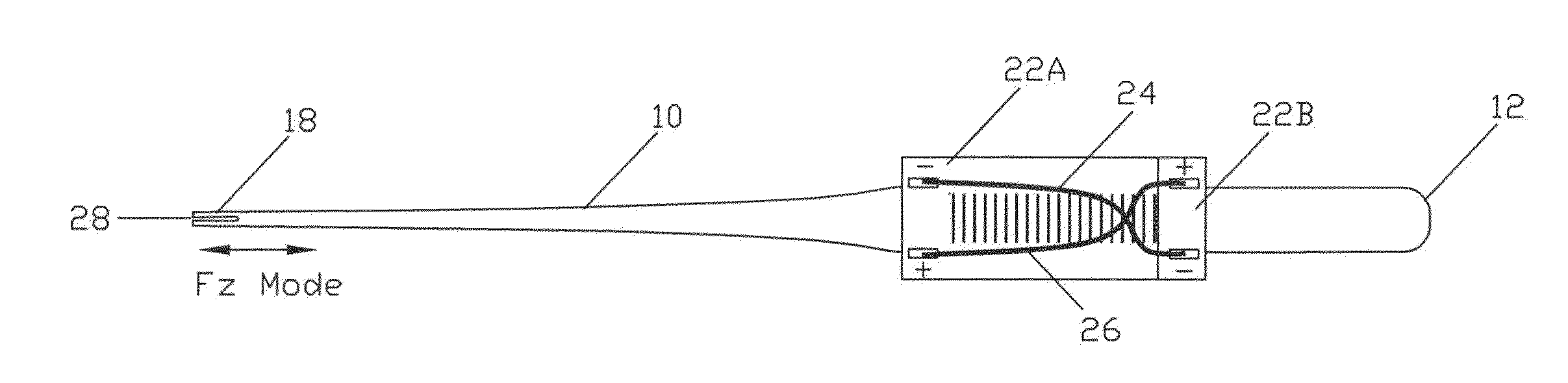
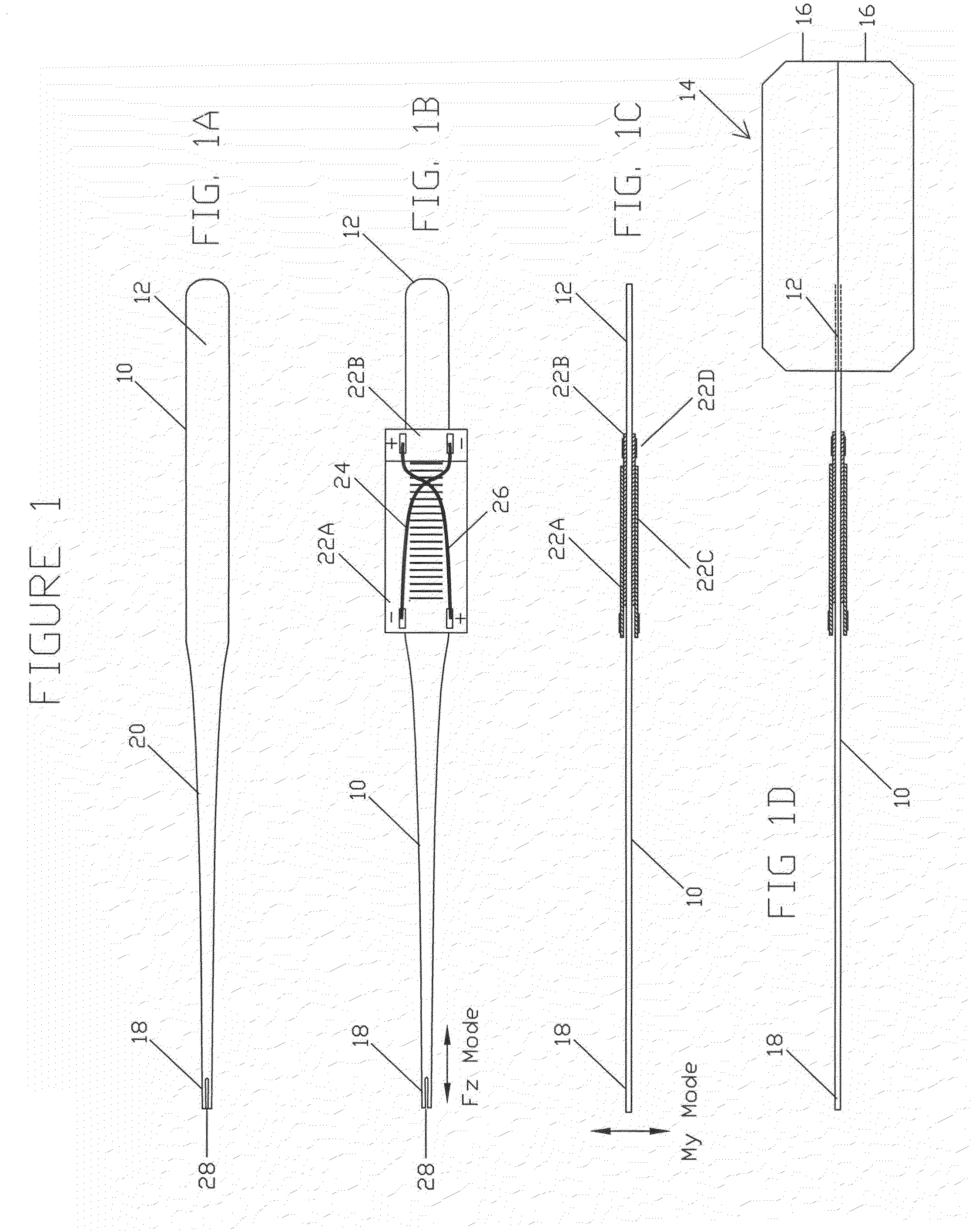
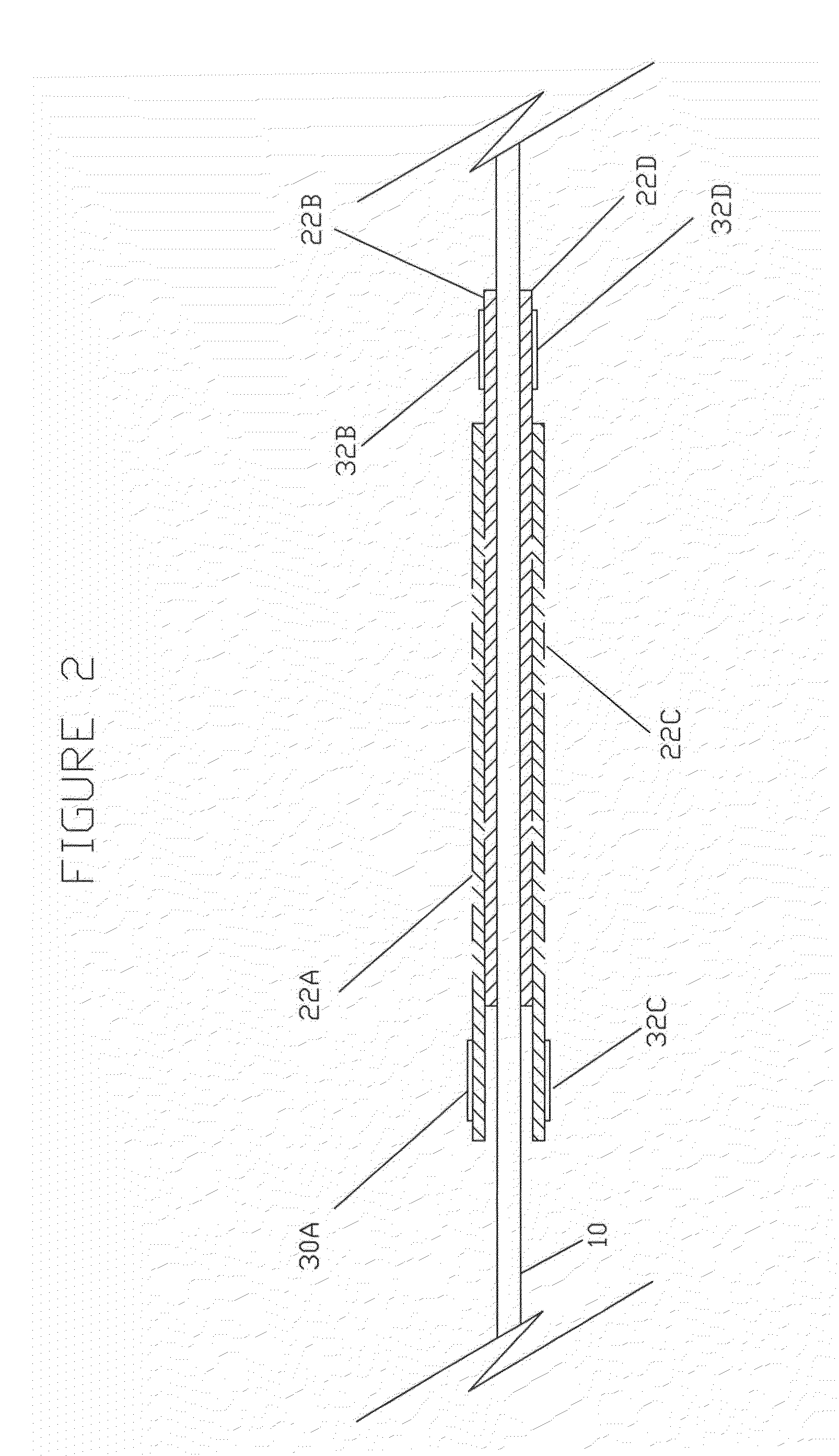
[0061]The present invention broadly employs a cantilevered beam, relatively rigidly supported at the proximal end and free to oscillate at the distal end, supporting MFCs on its surface which are electrically powered to induce a variety of motions of the distal end of the beam. A first preferred embodiment of the beam is illustrated in FIGS. 1A-1D.

[0062]The beam itself, indicated at 10 in FIGS. 1A-1D, is formed as a thin, generally flat beam formed of a sheet material, preferably stainless steel, but which could include other materials, in particular metals, which are relatively rigid such as titanium, aluminum, or materials such as graphene, Pyrex glass, or industrial diamonds. The beam 10 preferably has a relatively uniform thickness along its length, which may be in the range of 0.0040 to 0.0070 inch.

[0063]The relatively wide end of the beam, referred to as the proximal end 12, is relatively rigidly supported in a blocking mass generally indicated at 14 in FIG. 1D and consisting ...


PUM


Abstract

A surgical instrument for treating body tissues through narrow body passages employs an elongated cantilevered beam having a proximal end supported in a rigid block and a narrower distal end extendable through the narrow passages. One or more piezoelectric actuators are fixed to the beam surface and energized from an AC source through electrodes interspersed with the piezoelectric actuators to produce oscillatory motion of the beam distal end in multiple modes of movement with sensing electronics to monitor and control the distal mechanical movement.

Description

CROSS-REFERENCE TO RELATED APPLICATIONS[0001]This application claims priority of U.S. Provisional Application No. 61 / 950,924 filed Mar. 11, 2014, and U.S. Provisional Application No. 62 / 039,783 filed Aug. 20, 2014, the contents of which are incorporated herein by reference.FIELD OF THE INVENTION[0002]This invention relates to surgical instruments comprising cantilevered beams driven by macro fiber composites (MFCs) to destroy, dissect, incise, coagulate, and / or otherwise treat tissues through openings and passages to targets within a mammalian body.BACKGROUND OF THE INVENTION[0003]Energy driven surgical tools which apply acoustic energy to tissues can cause tissue effects deep in the body structures through relatively long, narrow passages. For deep and narrow surgery many devices and techniques have been developed and used. For example, cold knife techniques using knife blades or a rotating suction debrider such as marketed by Medtronics have been employed. The latter is an improve...

Claims


Application Information

Patent Timeline
Patent Type & Authority Applications(United States)
IPC IPC(8): A61B17/32
CPCA61B17/320068A61B2017/320096A61B2017/00141A61B2017/320072A61B17/22012A61B17/2202A61B17/24A61B2017/00734A61B2017/320098A61B2017/32007A61B2017/320082
Inventor HARRINGTON, RICKKRAPF, CHARLES W.RONTAL, MICHAELKLOCK, RYAN
Owner RONTAL MICHAEL DR
Why Eureka
Try Eureka