
Variable stiffness steering mechanism for catheters

a steering mechanism and variable stiffness technology, applied in the field of high-torque catheters, can solve the problems of not always conducive to the performance requirements of the necessary catheter, loss of light locally, and reduced sensitivity to detected strain, so as to achieve tight tolerance, control the curvature of the steering spine, and avoid sacrificing torsional strength

Active Publication Date: 2017-10-24
ST JUDE MEDICAL INT HLDG SARL
View PDF194 Cites 14 Cited by
  • Summary
  • Abstract
  • Description
  • Claims
  • Application Information

AI Technical Summary

Benefits of technology

The patent text discusses the use of small fiber optics in a catheter system to improve flexibility and reduce friction between components. The text also describes an elongate catheter assembly with a steering section that has a tapered steering spine made of rings and a continuous straight spine portion. The steering spine has varying flexibility along its length and slidingly engages with rings to provide torsional rigidity. The technical effects of the patent text include reducing the risk of over-flexing fiber optics and improving catheter system performance.

Problems solved by technology

The prior art generally provides a bend radius that is irregular and that is not always conducive to the necessary catheter performance requirements.
For example, with catheters that implement fiber optics, locally reduced bend radii generally causes a loss of light locally because of an effective reduction in the critical angle between the core fiber and the cladding.
The loss of light leads to reduced sensitivity to detected strain due to loss of signal.
Also, an excessively small local bend radius presents the risk of over-flexing the fiber optics and causing them to break.
However, smaller diameter fiber optics are also more fragile than larger diameter fiber optics.

Method used


Image

  • Variable stiffness steering mechanism for catheters
  • Variable stiffness steering mechanism for catheters
  • Variable stiffness steering mechanism for catheters

Examples


Embodiment Construction

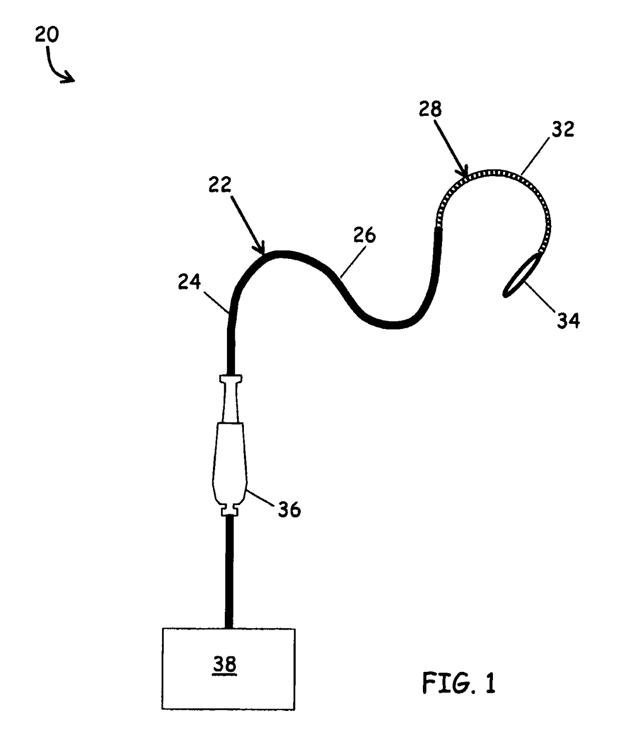
[0055]Referring to FIG. 1, a catheter system 20 is depicted in an embodiment of the invention. The catheter system 20 comprises an elongate catheter assembly 22 having a proximal portion 24, a middle portion 26 and a distal portion 28. The distal portion 28 includes a steering section 32 and an end effector 34. The catheter assembly 22 can include elongate internal components that extend through the proximal, middle and distal portions 22, 24 and 26, such as fiber optics, power leads, instrumentation leads, a pull wire and an irrigation lumen. In one embodiment, the proximal portion is operatively coupled with a handle 36. The handle 36 may be operatively coupled with various appurtenances 38 to augment the operation of the catheter system 20. Non-limiting examples of appurtenances 38 include power sources and / or irrigation systems for sourcing the end effector 34, electromagnetic sources for sourcing fiber optic systems within the catheter system 20, data acquisition devices for mo...


PUM

PropertyMeasurementUnit
diametersaaaaaaaaaa
diametersaaaaaaaaaa
divergence angleaaaaaaaaaa

Abstract

A catheter assembly including a tapered steering spine having a varying stiffness along an axial length. The tapered steering spine is tailored to provide increasing flexibility from proximal to distal in a way that makes the bend radius more uniform along the length of the steering section. In one embodiment, the tapered steering spine includes structures on adjacent rings that engage with each other when the steering section is flexed to limit the minimum bend radius to a predetermined minimum and which enhances the torsional rigidity of the steering section regardless of the degree of flexure of the steering section. The limited bend radius can prevent excessive bending of components such as fiber optics. The enhanced torsional rigidity can negate the need for torque braid in the section of the catheter shaft that surrounds the tapered steering spine.

Description

RELATED APPLICATIONS[0001]This application claims the benefit of U.S. Provisional Patent Application No. 61 / 322,627, filed on Apr. 9, 2010, and U.S. Provisional Patent Application No. 61 / 424,445, filed on Dec. 17, 2010, the disclosures of which are hereby incorporated by reference herein in their entirety.FIELD OF THE INVENTION[0002]The invention relates generally to a steerable ablation catheter system with a deflectable catheter tip for navigating through biological lumen. More specifically, the invention is directed to a high-torque catheter with a deflectable tip section comprised of a tapered steering spine.BACKGROUND[0003]Catheters are widely used to reach a desired site within the circulatory system of a patient, such the heart and adjacent arteries, to perform diagnostic or therapeutic medical procedures. Such catheters utilize a variety of designs to suit the requirements of specific medical procedures. In many cases, these catheters provide significant torsional rigidity w...

Claims


Application Information

Patent Timeline
Patent Type & Authority Patents(United States)
IPC IPC(8): A61M25/01A61M25/00A61B1/00A61B1/005
CPCA61M25/0147A61M25/0013A61M25/0053A61M25/0054A61B1/0055A61M2025/0059A61M25/0051A61M25/0052A61M25/0138A61M2025/0046A61B1/00078
Inventor ROMOSCANU, ALEXANDRE
Owner ST JUDE MEDICAL INT HLDG SARL
Learn More