Automated bit exchange method and apparatus for laboratory sample tube capping and decapping machines

a technology of automatic bit exchange and laboratory sample tube, which is applied in the direction of caps, instruments, glassware, etc., can solve the problems of time-consuming process and tedious process of exchanging adapter bits

Active Publication Date: 2017-10-24
HAMILTON STORAGE TECH
View PDF25 Cites 8 Cited by
  • Summary
  • Abstract
  • Description
  • Claims
  • Application Information

AI Technical Summary

Benefits of technology

[0005]The invention pertains to the use of an SBS-formatted bit exchange magazine that enables the automated replacement of adapter bits on a laboratory capper, decapper or combination capper / decapper. With the invention, adapter bits are exchanged more quickly and reliably.

Problems solved by technology

Screw caps on sample tubes can be removed manually but this is a tedious process.
The process of exchanging adapter bits is also time-consuming.

Method used


Image

  • Automated bit exchange method and apparatus for laboratory sample tube capping and decapping machines
  • Automated bit exchange method and apparatus for laboratory sample tube capping and decapping machines
  • Automated bit exchange method and apparatus for laboratory sample tube capping and decapping machines

Examples


Embodiment Construction

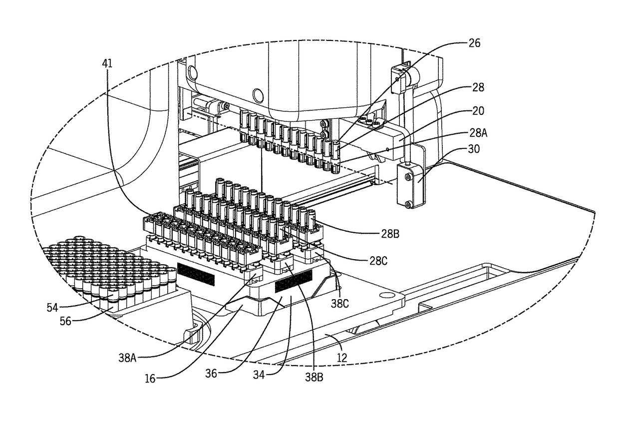
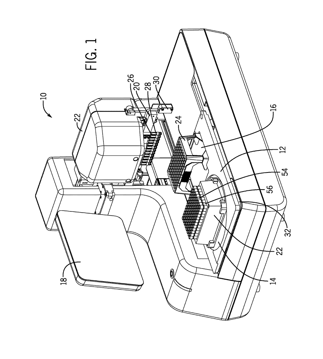
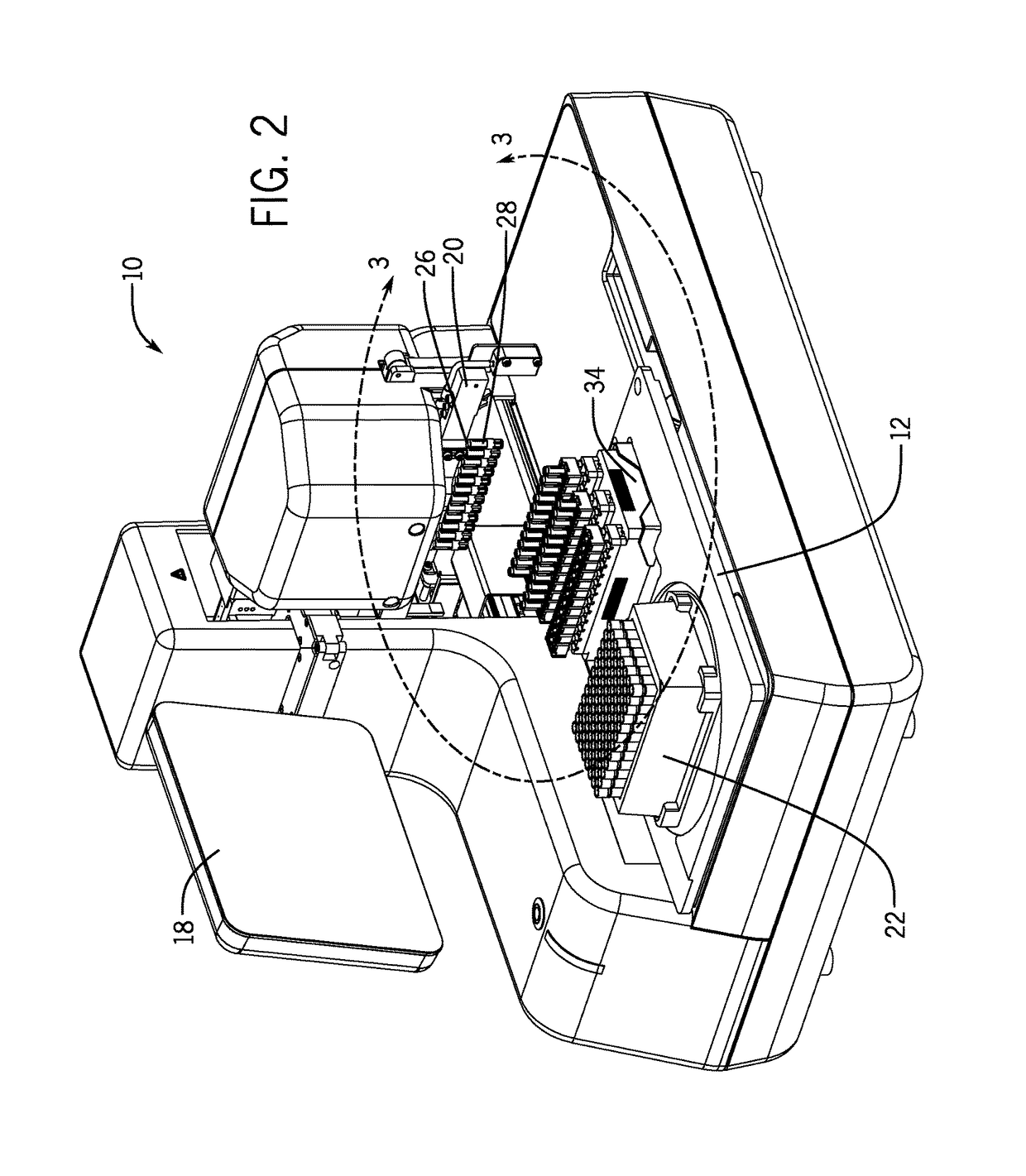
[0023]FIG. 1 illustrates a benchtop capper / decapper apparatus 10 for automated sample management. The capper / decapper apparatus 10 includes a deck 12 with a tube storage rack nest 14 and a second nest 16. A header 20 is located on a carriage 22 of the apparatus 10, and a row of 12 rotatable fittings 26 are located on the header 20. FIG. 1 shows adapter bits 28 mounted on the fittings 26. A touch screen 18 is used by the operator to program and control the operation of the apparatus 10. The apparatus 10 includes a drive mechanism to move the carriage 22 and the header 20 vertically along a Z-axis according to instructions programmed into the system. A drive mechanism in the apparatus 10 moves the deck 12 horizontally along a Y-axis.

[0024]In FIG. 1, an SBS-formatted, 96-tube storage rack 22 is set into the nest 14 on the deck 12. The tube storage rack 22 contains 96 sample tubes 56 in an 8×12 array, each with a screw cap 54. Nest 14 is on a turntable and is rotatable to change the ori...


PUM

PropertyMeasurementUnit
lengthaaaaaaaaaa
sizesaaaaaaaaaa
dimensionsaaaaaaaaaa

Abstract

A laboratory capper, decapper or combination capper / decapper includes a deck containing with a nest designed to hold an SBS-formatted tube storage rack, and a bit exchange magazine assembly containing one or more sets of adapter bits. The adapter bits are mounted on and unloaded from motor driven fittings, and are exchanged in order to cap or decap laboratory sample tubes or vials that have different head configurations. The bit exchange magazine assembly enables the bit to be exchanged robotically.

Description

FIELD OF THE INVENTION[0001]The invention pertains to the exchange of adapter bits on benchtop instruments that automatically screw caps on or off of laboratory sample tubes.BACKGROUND OF THE INVENTION[0002]Laboratory sample tubes, sometimes called microtubes or cryovials, are normally stored in SBS-formatted storage racks. One of the most common sizes is a 96-tube storage rack which includes eight rows and twelve columns of tube receptacles for holding 96 sample tubes. SBS format standards petinent to tube storage racks are ANSI / SLAS 1-2004 (footprint dimensions, e.g., 85.48 mm ×127.76 mm) and ANSI / SLAS 4-2004 (well positions, e.g. 9 mm spacing for 8×12 well array). Storage racks designed to hold larger sample tubes typically hold 48 or 24 tubes. The sample tubes normally have screw caps to seal the top of tubes. A 2-D barcode is often printed on the bottom of the tubes for automated tracking purposes. Most storage racks contain openings in the bottom of the rack to enable a barcod...

Claims


Application Information

Patent Timeline
Patent Type & Authority Patents(United States)
IPC IPC(8): B67B3/20B23Q3/157B67B7/18G01N35/04B01L3/00B23Q3/155
CPCB67B3/208B01L3/50825B23Q3/15506B23Q3/15786B67B3/2053B67B7/182B67B3/2066Y10T483/1845B23Q2003/15537B67B2201/10G01N2035/0405
Inventor FREY, MARTINTHONY, BEATZAHNER, BEATTAPPE, PETRA
Owner HAMILTON STORAGE TECH
Why Eureka
Try Eureka