Vehicle seat slide mechanism

a technology of seat assembly and slide mechanism, which is applied in the direction of machine supports, movable seats, other domestic objects, etc., can solve the problems of increasing the cost of the vehicle seat, reducing the distance that the seat assembly moves away from the head of the occupant, and the amount of tilting motion of the seat assembly can be more effectively limited, so as to reduce the tilting motion, reduce the rearward tilting movement, and reduce the effect of the seat assembly movement distan

Active Publication Date: 2017-10-31
TOYOTA BOSHOKU KK
View PDF26 Cites 5 Cited by
  • Summary
  • Abstract
  • Description
  • Claims
  • Application Information

AI Technical Summary

Benefits of technology

[0009]For example, it is often the case that as an impact is applied to the rear side of the vehicle, the weight of the occupant on the vehicle seat acts, due to the inertial force, on the seat assembly, and thus the occupant presses the seat assembly rearward. At this time, force is transferred to the upper rail from the seat assembly, resulting, for example, in the upper rail deforming to entirely, or partially, tilt, so that a part of the upper rail moves toward the lower rail. Such movement of the upper rail toward the lower rail is restricted by the upper rail hitting against the gap reduction member, that is, the tilting motion of the upper rail is reduced by the gap reduction member. As such, the gap reduction member reduces the tilting motion of the upper rail and thus reduces the rearward tilting movement, caused by the same tilting motion of the upper rail, of the seat assembly, resulting in a decrease in the distance that the seat assembly moves away from the head of the occupant. Accordingly, the head of the occupant is immediately received by the seat assembly, and thus the possibility of whiplash of the occupant is reduced.
[0010]In the meantime, conventionally, typical measures for preventing or reducing whiplash have been to increase the strengths of some parts of a seat assembly of a vehicle seat, such as increasing the thickness of the parts, using stronger materials for them, and shaping them to be higher in strength, however such measures are costly, causing an increase in the cost of the vehicle seat. On the other hand, a gap reduction member, such as the one described above, is simple in structure but is capable of restricting the tilting motion of the seat assembly, at the slide mechanism about which the seat assembly tilts when an impact is applied to the vehicle seat, for example. Therefore, the amount of the tilting motion of the seat assembly can be more effectively limited than in cases where a structure, arrangement, and the like, for coping with the tilting motion of the seat assembly is provided out of or distant from the center of the tilting motion of the seat assembly.

Problems solved by technology

As such, the gap reduction member reduces the tilting motion of the upper rail and thus reduces the rearward tilting movement, caused by the same tilting motion of the upper rail, of the seat assembly, resulting in a decrease in the distance that the seat assembly moves away from the head of the occupant.
In the meantime, conventionally, typical measures for preventing or reducing whiplash have been to increase the strengths of some parts of a seat assembly of a vehicle seat, such as increasing the thickness of the parts, using stronger materials for them, and shaping them to be higher in strength, however such measures are costly, causing an increase in the cost of the vehicle seat.
Therefore, the amount of the tilting motion of the seat assembly can be more effectively limited than in cases where a structure, arrangement, and the like, for coping with the tilting motion of the seat assembly is provided out of or distant from the center of the tilting motion of the seat assembly.

Method used


Image

  • Vehicle seat slide mechanism
  • Vehicle seat slide mechanism
  • Vehicle seat slide mechanism

Examples


Embodiment Construction

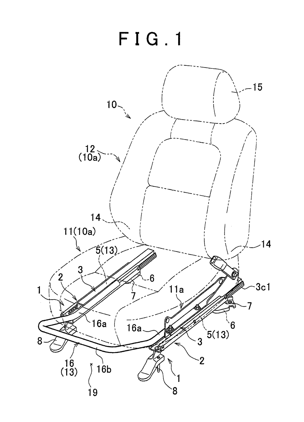
[0017]An example embodiment of the invention will hereinafter be described with reference to FIGS. 1 to 5. Referring to FIG. 1, a vehicle seat 10 has a seat assembly 10a and a pair of slide mechanisms 1. The seat assembly 10a has a seat cushion 11 and a seatback 12. The seatback 12 is connected to the rear side of the seat cushion 11 via a reclining device 14, so that the seatback 12 is tiltable with respect to the seat cushion 11. A headrest 15 is provided on the top of the seatback 12. Support members 11a are provided at the lower sides of the left and right edges of the seat cushion 11, respectively. The support members 11 a are attached on upper rails 3 of the respective slide mechanisms 1.

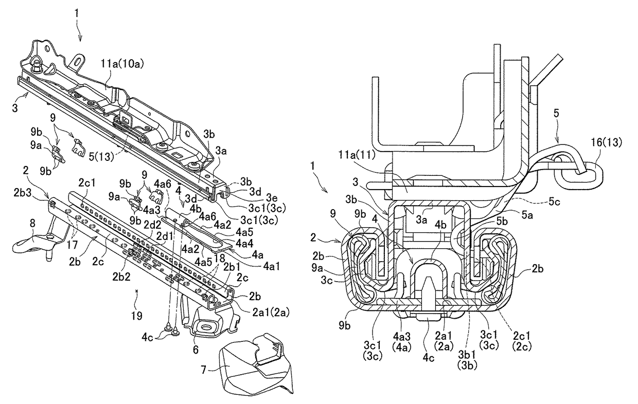
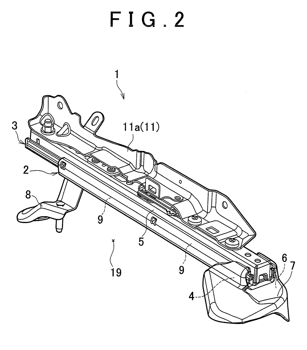
[0018]Referring to FIGS. 2 and 3, the slide mechanisms (seat tracks) 1 each have a lower rail 2 mounted on a floor 19 of the vehicle and the upper rail 3 slidably attached on the lower rail 2. Note that the lower rail 2 and the upper rail 3 extend in the longitudinal direction of the vehicle s...


PUM


Abstract

A vehicle seat slide mechanism via which a seat assembly is slidably mounted on a vehicle floor is provided with: a lower rail that is mounted on the vehicle floor; an upper rail which is slidably attached on the lower rail and on which the seat assembly is attached; a lock mechanism that locks the upper rail on the lower rail in a releasable manner; and a gap reduction member that is provided between a first face formed at the lower rail and facing in a substantially vertical direction and a second face formed at the upper rail and facing to the first face.

Description

INCORPORATION BY REFERENCE[0001]The disclosure of Japanese Patent Application No. 2011-007832 filed on Jan. 18, 2011 including the specification, drawings and abstract is incorporated herein by reference in its entirety.BACKGROUND OF THE INVENTION[0002]1. Field of the Invention[0003]The invention relates to a vehicle seat slide mechanism via which a seat assembly is slidably mounted on the floor of a vehicle.[0004]2. Description of Related Art[0005]A vehicle seat slide mechanism has a lower rail mounted on the floor of a vehicle, an upper rail which is slidably attached on the lower rail and on which a seat assembly is attached, a lock mechanism that locks the upper rail on the lower rail in a releasable manner, and stoppers that define a range over which the upper rail is slidable relative to the lower rail (For example, refer to Japanese Patent No. 3520510).[0006]However, there have been various demands for adding new functions to vehicle seat slide mechanisms.SUMMARY OF THE INVEN...

Claims


Application Information

Patent Timeline
Patent Type & Authority Patents(United States)
IPC IPC(8): B60N2/07B60N2/08
CPCB60N2/0705B60N2/0843B60N2/0818B60N2/0722
Inventor MATSUSHIMA, IWAO
Owner TOYOTA BOSHOKU KK
Why Eureka
Try Eureka