Shaft, particularly a partly tubular camshaft

a camshaft and partly tubular technology, applied in the direction of crankcase ventillation, machine/engine, valve arrangement, etc., can solve the problems that the splash guard rotation cannot be completely prevented under certain conditions, and the droplets of large oil cannot follow the rotation of the splash guard to the same extent, so as to increase the flow rate and prevent excessive overpressure

Active Publication Date: 2017-10-31
THYSSENKRUPP PRESTA TECCENTER AG
View PDF15 Cites 2 Cited by
  • Summary
  • Abstract
  • Description
  • Claims
  • Application Information

AI Technical Summary

Benefits of technology

[0022]As explained above, it is advantageous to provide a separate oil separator to separate the fine oil droplets from the blowby gas, which separator can be mounted inside the tubular shaft part. To accomplish this, a spiral swirl generator can be provided, for example, formed with one or more spiral passages, so that the fine oil droplets of the blowby gas are s thrown outward by the swirl motion and thus separated. By varying the pitch of the spiral passages, it is also possible to increase the flow rate in the direction of flow.
[0023]A bypass valve including a bypass passage connected thereto can also be provided inside the tubular shaft part in order to prevent excessive overpressure at the camshaft, the passage diverting the blowby gas past the oil separator.

Problems solved by technology

Another significant factor is that large oil droplets and splashed oil are not able to follow the rotation of the splash guard to the same extent as the blowby gas.
As the volumetric flow rate of the blowby gas increases, a situation cannot under certain conditions be completely prevented whereby relatively large oil droplets are entrained and reach the tubular shaft part.

Method used


Image

  • Shaft, particularly a partly tubular camshaft
  • Shaft, particularly a partly tubular camshaft
  • Shaft, particularly a partly tubular camshaft

Examples


Embodiment Construction

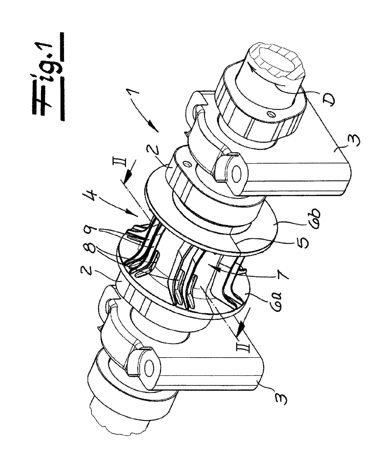
[0029]FIG. 1 shows an installation-ready camshaft assembly comprising a camshaft 1 with a plurality of cams 2 of typical is construction and mounted in bearing or pillow blocks 3. A splash guard 4 is provided between adjacent cams 2, the function of the splash guard being explained in more detail below.

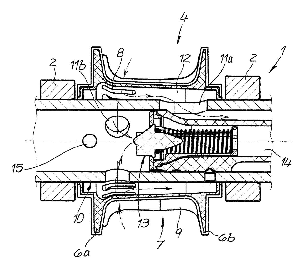
[0030]FIG. 1 shows here that the splash guard 4 is formed by two segments joined at an interface 5. Also shown is the fact that the splash guard 4 has flange-like widened ends 6a and 6b and a tubular, essentially cylindrical center section 7 therebetween. Holes 8 formed as axially extending slots, as well as projections formed as ribs 9 are seen that run axially of the shaft.

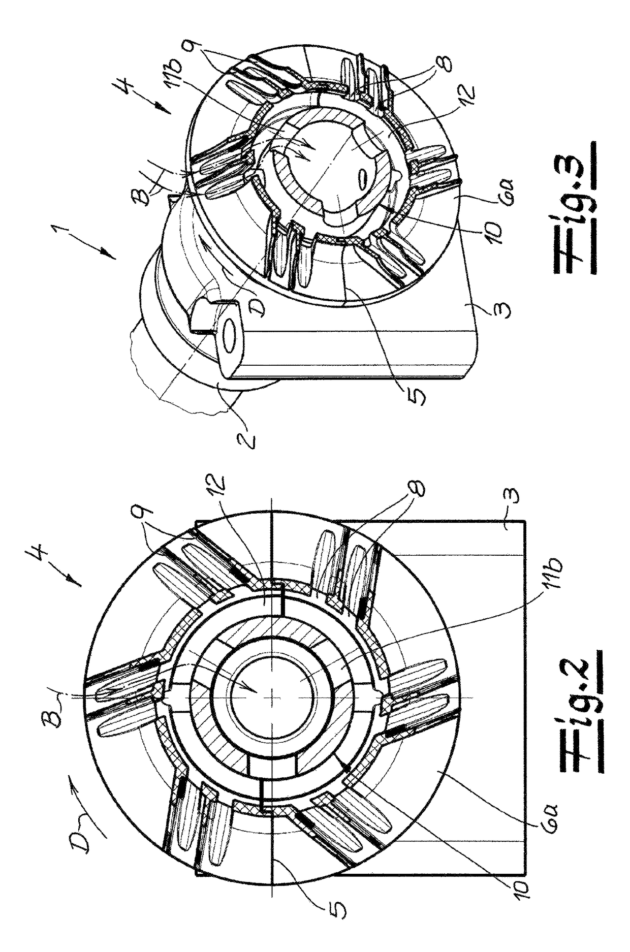
[0031]The purpose of the splash guard 4 and the exact configuration of the camshaft 1 is shown in FIGS. 2 through 4. FIGS. 2 and 3 are similar cross-sections, the precise orientation of the ribs 9 and of the holes 8 being shown in the end cross-sectional view of FIG. 2. The perspective view of FIG. 3, on the other...


PUM


Abstract

The invention relates to a shaft, particularly a cam shaft (1), comprising a hollow shaft section (10) with at least one radial inlet opening (11a, 11b) for evacuating a gas through said hollow shaft section (10), and comprising a splash-guard device (4) arranged in the region of the radial inlet opening (11a, 11b) on the hollow shaft section (10). According to the invention, the splash-guard device (4) has a radially exposed cover with radial passage openings (8) and protrusions between said passage openings (8). The protrusions can, in particular, be in the form of ribs (9).

Description

CROSS REFERENCE TO RELATED APPLICATIONS[0001]This application is the US-national stage of PCT application PCT / EP2012 / 051800 filed 2 Feb. 2012 and claiming the priority of German patent application 102011000458.0 itself filed 2 Feb. 2011.FIELD OF THE INVENTION[0002]The invention relates to a shaft, in particular, a camshaft having a tubular part that has at least one radial intake port for conducting a gas through the tubular shaft part, and comprising a splash guard that is mounted on the tubular shaft part at the radial intake port.BACKGROUND OF THE INVENTION[0003]Practical experience has revealed leakage losses in combustion engines and piston compressors that can be attributed to an incomplete seal. These leakage losses are identified as blowby gas and contain a significant amount of oil. The common approach with combustion engines is therefore to pass the blowby gas accumulating in the valve chamber back into the intake of the combustion engine. A known means for both the loss o...

Claims


Application Information

Patent Timeline
Patent Type & Authority Patents(United States)
IPC IPC(8): F01L1/047F01M13/04F01L1/46F02B67/06
CPCF01L1/047F01L1/46F01M13/04F02B67/06Y10T74/2101F01L2001/0475F01L2001/0476F01M2013/0422
Inventor MUELLER, ULF
Owner THYSSENKRUPP PRESTA TECCENTER AG
Why Eureka
Try Eureka