Conduit connector for a patient breathing device

a patient breathing device and connector technology, applied in the field of connectors for gas delivery hoses, can solve the problems of increasing the potential variance between the sampled air and the air inhaled by the patient, patient discomfort or limiting the airflow of the cannula, and achieve the effect of increasing patient comfor

Active Publication Date: 2017-11-07
FISHER & PAYKEL HEALTHCARE LTD
View PDF17 Cites 32 Cited by
  • Summary
  • Abstract
  • Description
  • Claims
  • Application Information

AI Technical Summary

Benefits of technology

[0005]In some situations, a nasal cannula is used to provide humidified airflow or oxygen therapy. In order to monitor the airflow being received by the patient, a sensor probe can be used. However, the further the distance of the probe from the prongs that provide air to the nostrils, the greater the potential variance between the sampled air and the air inhaled by the patient. Thus, a conduit connector that places the sensor probe in the airflow closer to the patient can enhance the accuracy of the measurements taken.
[0006]As a nasal cannula or other breathing device can be connected to a patient for extended periods of time, the nasal cannula can generate discomfort for the patient or otherwise begin to perform sub-optimally. For example, as the patient moves around in a hospital bed, the nasal cannula tubing can become tangled or twisted, thereby causing the patient discomfort or limiting the airflow within the cannula. Thus, a design that facilitates adjustments of the nasal cannula can provide greater comfort to the patient or improve performance.
[0007]At times, the nasal cannula or an airflow source may need to be removed or replaced. If detaching the nasal cannula from the airflow source is difficult or time consuming, detaching the nasal cannula may cause significant discomfort for the patient. Further, in emergencies, a slow or difficult connection mechanism can potentially place the patient's health in danger. Thus, a conduit connector that provides a “quick-connect” or “quick-release” feature that facilitates attachment and detachment of the nasal cannula from an airflow source, as well as facilitating interchangeability of components, can provide greater comfort and / or safety.
[0009]Aspects of the present disclosure also include a self-aligning connector assembly configured to automatically align locking protrusions on a first component with locking recesses on a second component, wherein insertion of the second component within the first component causes the second component to rotate relative to the first component, thereby aligning the locking protrusions with associated locking recesses. In an embodiment, the connector is configured to advantageously allow the nasal cannula to rotate relative to the gas delivery hose. By allowing rotation, the connector enables a patient or healthcare provider to untangle or otherwise straighten the hose or the cannula, thereby increasing patient comfort.

Problems solved by technology

However, the further the distance of the probe from the prongs that provide air to the nostrils, the greater the potential variance between the sampled air and the air inhaled by the patient.
As a nasal cannula or other breathing device can be connected to a patient for extended periods of time, the nasal cannula can generate discomfort for the patient or otherwise begin to perform sub-optimally.
For example, as the patient moves around in a hospital bed, the nasal cannula tubing can become tangled or twisted, thereby causing the patient discomfort or limiting the airflow within the cannula.
If detaching the nasal cannula from the airflow source is difficult or time consuming, detaching the nasal cannula may cause significant discomfort for the patient.
Further, in emergencies, a slow or difficult connection mechanism can potentially place the patient's health in danger.

Method used


Image

  • Conduit connector for a patient breathing device
  • Conduit connector for a patient breathing device
  • Conduit connector for a patient breathing device

Examples


Embodiment Construction

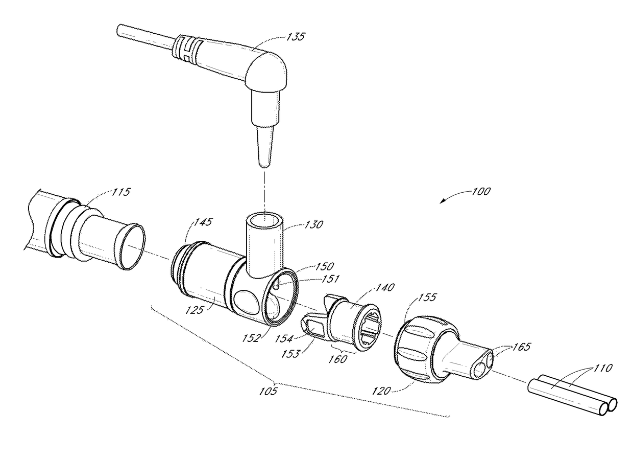
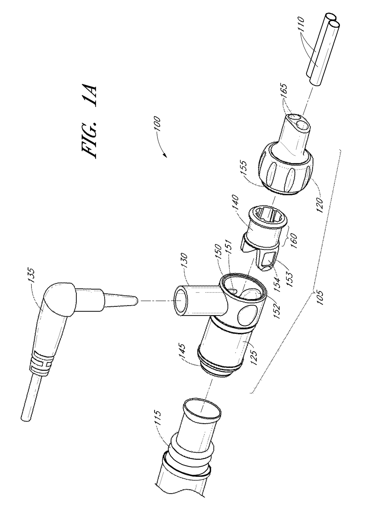
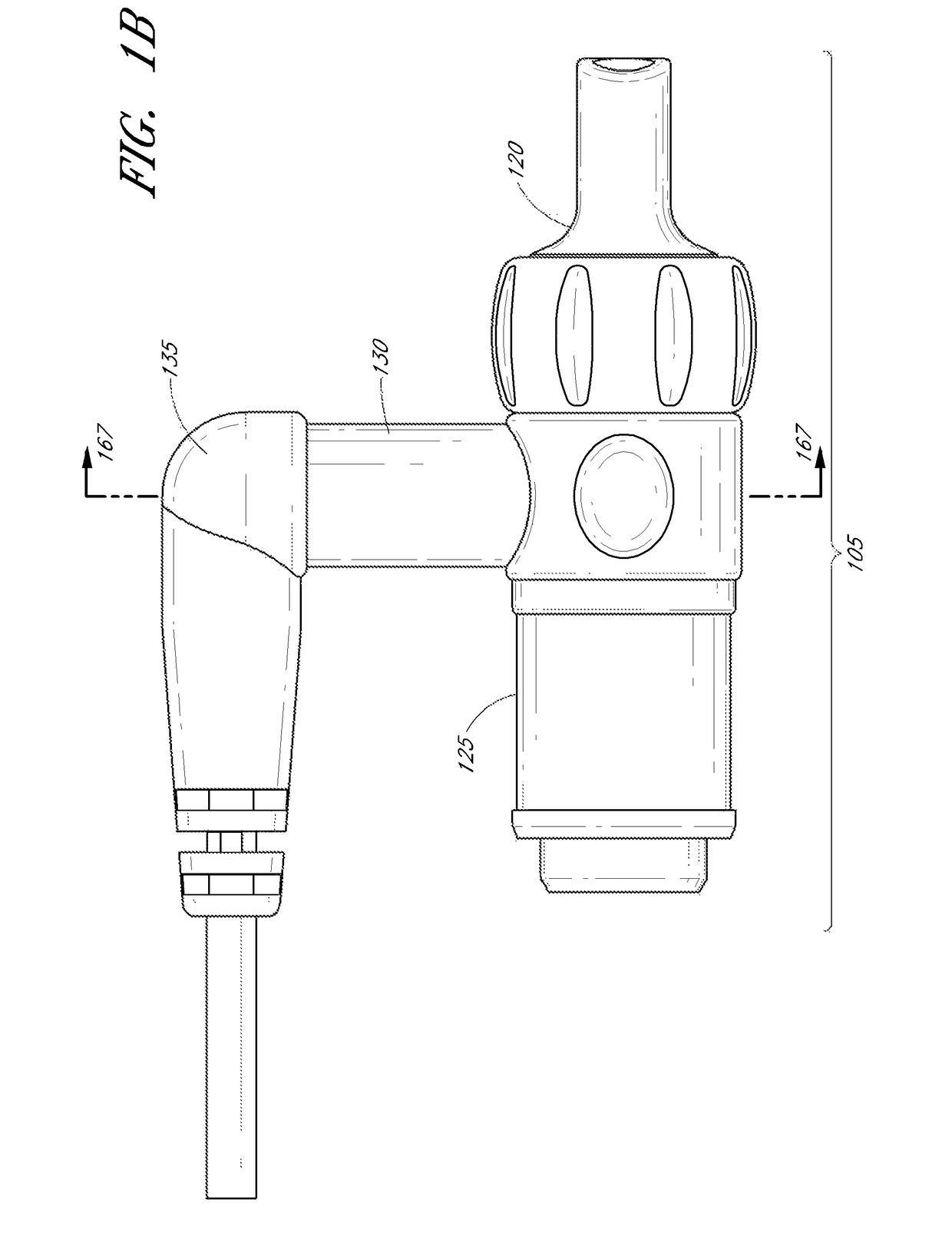
[0028]FIGS. 1A and 1B illustrate a perspective view and side view, respectively, of a gas delivery conduit 100 comprising an embodiment of a connector 105 for attaching a first tube 110 from a nasal cannula, face mask, intubation tube or other breathing device for a patient with a second tube 115 from a respirator, humidifier, breathing circuit, or other airflow device for providing gas to the patient. The connector can allow components of the gas delivery conduit 100 to be connected or disconnected from each other, thus facilitating disconnection and reconnection of the breathing device and airflow device with potentially minimal disturbance to the patient or gas delivery system.

[0029]For example, a patient can receive humidified, oxygenated and / or pressurized gases through a nasal cannula 110 connected to the gas delivery tube 115 that in turn is connected to a humidifier or respirator. For ease of explanation, the following disclosure refers to embodiments of the connector for co...


PUM


Abstract

In an embodiment, a connector or connector assembly for attaching a nasal cannula with a gas delivery hose includes a sensor port for a sensor probe positioned near an end of a nasal cannula, which can allow the sensor probe to be placed closer to the patient's nostrils than previous connector parts allowed. The connector can be configured to advantageously allow the nasal cannula to rotate relative to the gas delivery hose, thereby allowing a patient or healthcare provider to untangle or otherwise straighten the hose or the cannula. The connector assembly can be configured to automatically align locking protrusions on a first component with locking recesses on a second component, where insertion of the second component within the first component causes the second component to rotate relative to the first component, thereby aligning the locking protrusions with associated locking recesses.

Description

CROSS-REFERENCE TO RELATED APPLICATIONS[0001]This application is a national phase of International Application No. PCT / NZ2012 / 000142, filed Aug. 10, 2012, which claims priority from U.S. Provisional App. No. 61 / 521,972, filed Aug. 10, 2011. Each of the applications referenced in this paragraph is incorporated by reference herein in its entirety.FIELD OF THE DISCLOSURE[0002]This disclosure relates to the field of connectors for gas delivery hoses.BACKGROUND OF THE DISCLOSURE[0003]A nasal cannula is a device used to deliver supplemental oxygen, other gases, or airflow to a patient or person for treatment or for aiding respiration. Typically, the cannula includes a plastic tube and a set of two prongs which are placed in the nostrils. Oxygen or other gases can flow from these prongs.[0004]The nasal cannula can be connected to an oxygen tank, a portable oxygen generator, a wall connection in a hospital via a flowmeter, or other gas source. Nasal cannulas can supply oxygen to a patient a...

Claims


Application Information

Patent Timeline
Patent Type & Authority Patents(United States)
IPC IPC(8): A61M39/10A61M16/06A61M16/08A61B5/08A61M16/16A61M16/00A61M16/10
CPCA61M39/1011A61M16/0666A61M16/085A61M16/0816A61M16/0825A61M16/0833A61M16/0841A61M16/161A61B5/082A61M2209/088A61M16/0875A61M2016/0033A61M2016/102A61M2016/103A61M2016/1025A61M2039/1027A61M2039/1044A61M2205/3368A61M2205/581A61M2205/584A61M2205/6045A61M16/00A61M16/0003A61M2202/0208A61M2210/0618A61M2210/005A61M16/0672A61M39/10A61M39/1055A61M16/021A61M16/0051A61M2039/1077
Inventor GULLIVER, LAURENCERONAYNE, MICHAEL PAULIRVING, CHARLES WILLIAM DOUGLAS
Owner FISHER & PAYKEL HEALTHCARE LTD
Why Eureka
Try Eureka