Resonant load power conversion device and time division operation method for resonant load power conversion device

a power conversion device and resonant load technology, applied in the direction of power conversion systems, efficient power electronics conversion, climate sustainability, etc., can solve the problems of loss increase and damage of switching devices, and achieve the effect of reducing the number of main circuit conductors, reducing the cost of the apparatus, and reducing the switching frequency of each switching devi

Active Publication Date: 2017-11-07
MEIDENSHA ELECTRIC MFG CO LTD
View PDF12 Cites 2 Cited by
  • Summary
  • Abstract
  • Description
  • Claims
  • Application Information

AI Technical Summary

Benefits of technology

[0023]The present invention has been devised to solve these problems. It is an object of the present invention to provide a power conversion apparatus for a resonant load and its time-division operating method, for lowering the switching frequency of each switching device and decreasing the number of main circuit conductors between the dc input section Vdc and the dc input side terminal of each switching device of the upper and lower arms and between the square wave voltage output section Vout and the output terminal of each switching device of the upper and lower arms.
[0068](2) It is possible to avoid the limitation on the output frequency by the limit of the minimum pulse width determined by the properties of the device according to the invention recited in Claim 2 or 4 because the on or off period during which each switching device is held on or off by the gate command signal produced by the gate command generating section is continuous for a plurality of clocks or a plurality of clock intervals.

Problems solved by technology

Consequently, the zero cross point of the current flowing through each main circuit component deviates and the loss is increased by an increase of the current flowing in an unillustrated snubber circuit connected with each switching device.
Moreover, the increase of the snubber current might cause damage of the switching device.

Method used


Image

  • Resonant load power conversion device and time division operation method for resonant load power conversion device
  • Resonant load power conversion device and time division operation method for resonant load power conversion device
  • Resonant load power conversion device and time division operation method for resonant load power conversion device

Examples


Embodiment Construction

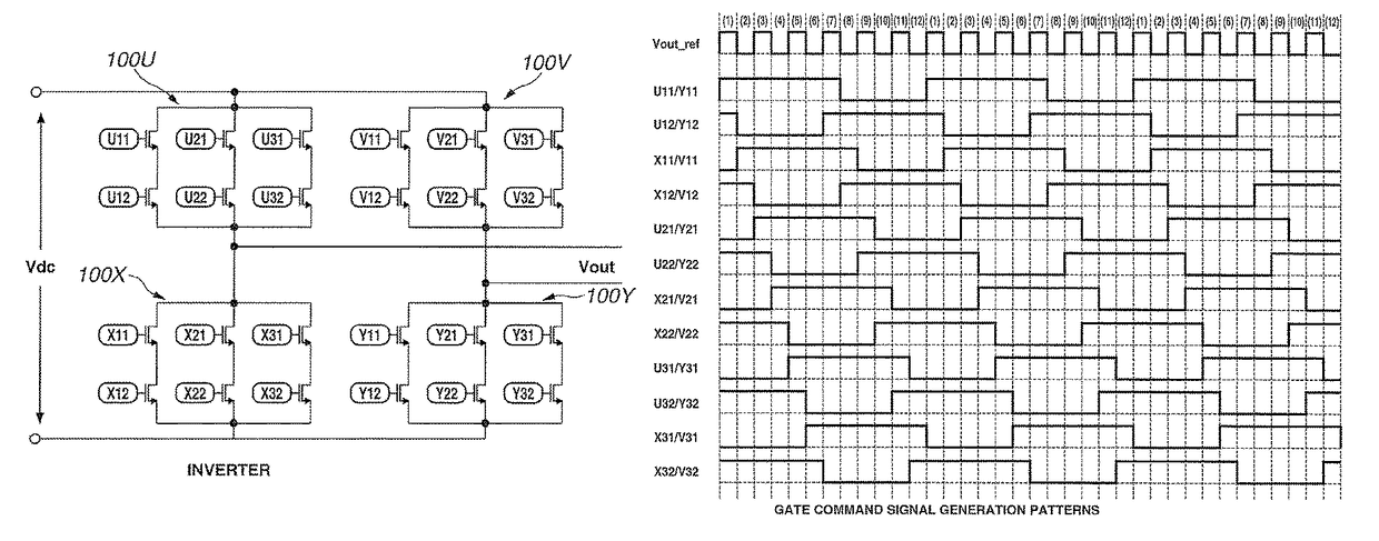
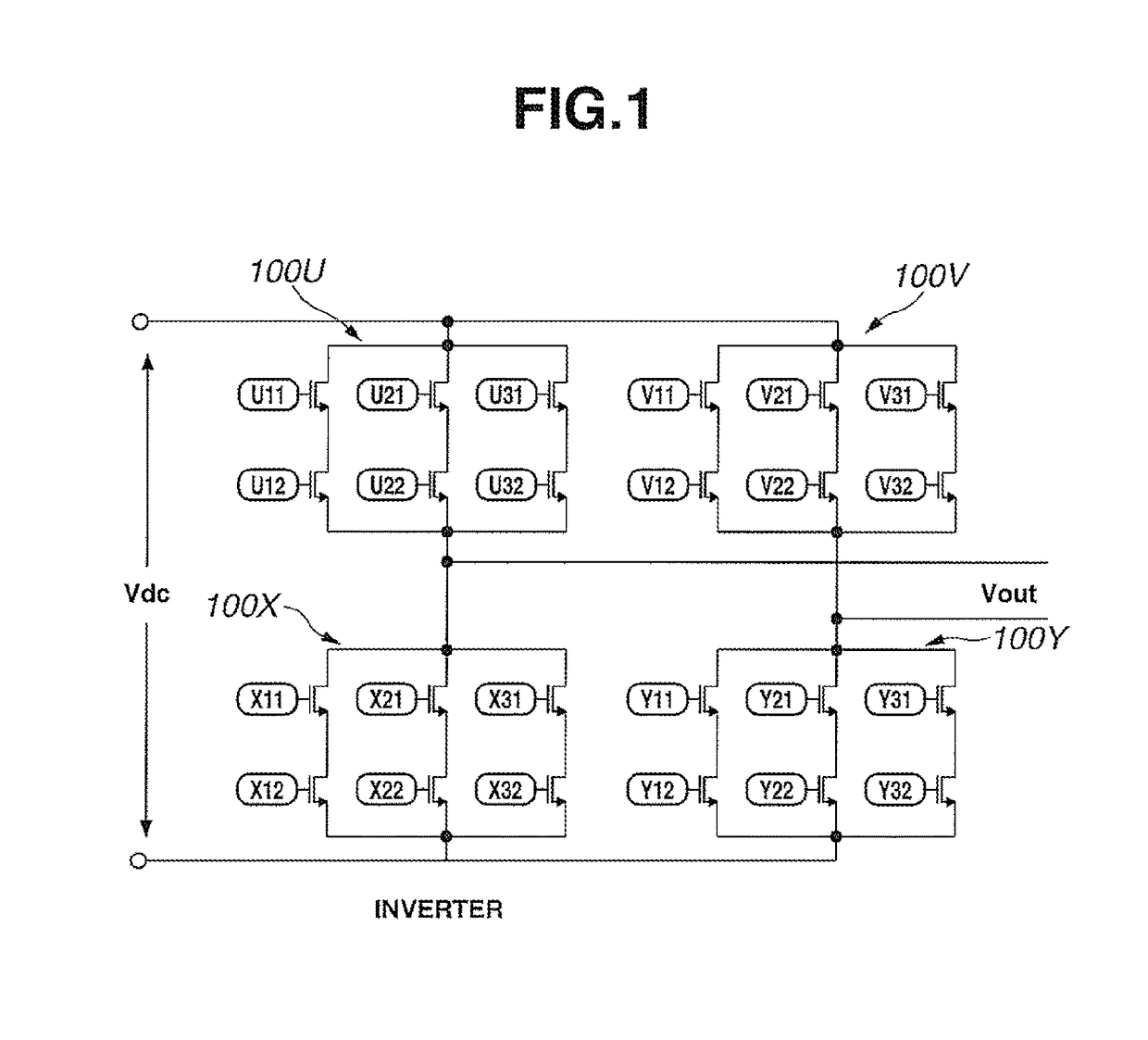
[0077]Although embodiment or embodiments of the present invention is explained hereinbelow with reference to the drawings, the present invention is not limited to the following embodiment. FIG. 1 shows the configuration of a single-phase inverter section according to an embodiment of the present invention. This single-phase inverter can be used as the ac / dc conversion apparatus 10 (power converter for a resonant load) of FIG. 5, for example.

[0078]A dc input section of the single-phase inverter of FIG. 1 is connected with a dc link voltage input section Vdc. Switch group circuits 100U, 100V, 100X and 100Y are connected, respectively, in arms of the single-phase inverter. Each of the switch group circuits includes switching devices (IGBT, for example) arranged in a M series N parallel array (2 series 3 parallel in the example of FIG. 1). A rectangular or square wave output voltage Vout is outputted from between a common connection point of the switch group circuits 100U and 100X and a...


PUM


Abstract

A resonant load power conversion apparatus is provided to lower a switching frequency of each switching device and to reduce the number of main circuit conductors. The conversion apparatus includes a single-phase inverter having a dc input side (Vdc) connected with a dc voltage source and an output side (Vout) connected with a resonant load and outputting a rectangular wave voltage with a resonance frequency. Upper and lower arms on the input side and output side of the single-phase inverter are connected, respective, with switch group circuits 100U, 100V, 100V and 100V each of which includes N series combinations (N is an integer equal to or greater than 2) of two switching devices, connected in parallel with each other by main circuit conductors. The switching devices of the switch group circuits are controlled in a time division switching control mode with a control section.

Description

TECHNICAL FIELD[0001]The present invention relates to a load resonance power conversion apparatus for supplying a voltage having a rectangular or square waveform to a resonant load such as an induction heating circuit.BACKGROUND ART[0002]FIG. 5 shows the circuit configuration of a load resonance power conversion apparatus (ac / dc conversion apparatus) connected with a resonant load. In FIG. 5, an ac / dc conversion apparatus or converter 10 is provided with a single-phase inverter having an input side connected with a dc voltage source 11, and an output side connected with a resonant load 12 such as an inductive heating circuit. The conversion apparatus 10 outputs a rectangular or square voltage at a resonance frequency to the resonant load 12 by on / off control of each switching device of the single-phase inverter.[0003]In the case of the resonant load 12 being an induction heating circuit, this ac / dc conversion apparatus 10 is constructed as an induction heating load resonance ac / dc c...

Claims


Application Information

Patent Timeline
Patent Type & Authority Patents(United States)
IPC IPC(8): H02M1/00H02M1/088H02M7/537
CPCH02M7/537H02M1/088H02M1/0043Y02B70/10
Inventor KONDO, YASUHIRO
Owner MEIDENSHA ELECTRIC MFG CO LTD
Why Eureka
Try Eureka