
Actuation device, in particular electronic actuator

a technology of actuation device and electronic actuator, which is applied in the direction of magnets, machines/engines, magnets, etc., can solve the problems of heat entering the housing, adversely affecting the actuation shank itself,

Active Publication Date: 2017-11-21
BORGWARNER INC
View PDF12 Cites 3 Cited by
  • Summary
  • Abstract
  • Description
  • Claims
  • Application Information

AI Technical Summary

Benefits of technology

The invention is a shielding cap that can protect against contamination and prevent fouling of the actuation device. It can be easily installed without the need for additional fastening means and can be directly screwed between the actuation device and the actuator bracket. This results in a more efficient and effective shielding solution.

Problems solved by technology

The actuation shank of such actuation devices may warm up owing to high ambient temperatures, such as for example in an engine bay, which firstly can adversely affect the actuation shank itself and secondly can result in an introduction of heat into the housing of the actuation device as a result of heat conduction via the actuation shank.

Method used


Image

  • Actuation device, in particular electronic actuator
  • Actuation device, in particular electronic actuator
  • Actuation device, in particular electronic actuator

Examples


Embodiment Construction

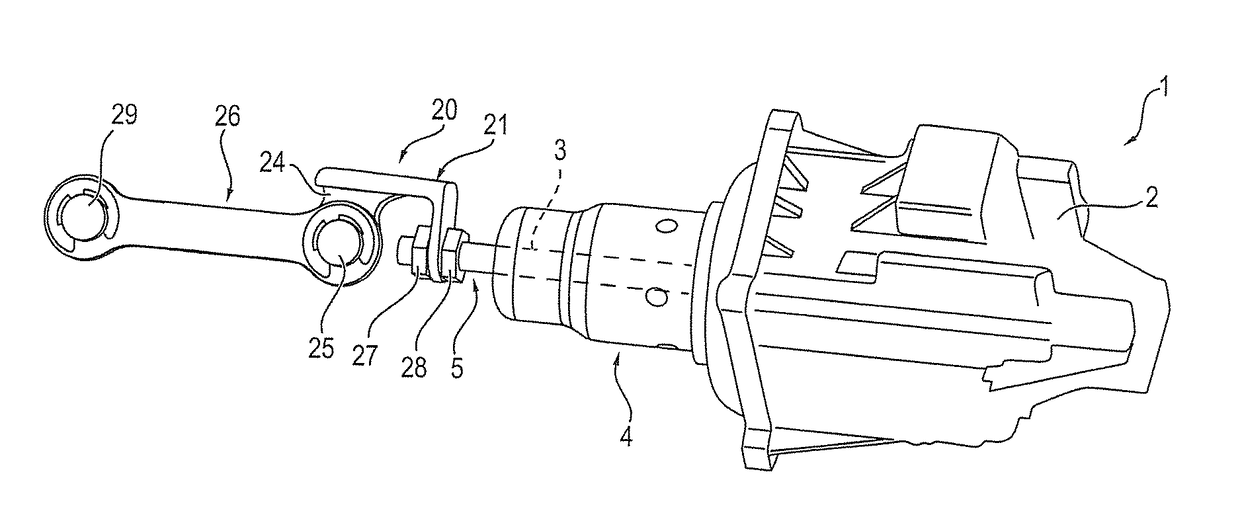
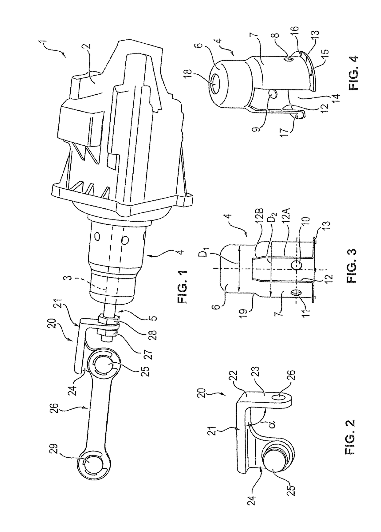
[0019]FIG. 1 illustrates an actuation device 1 according to the invention which, in the example, is in the form of an electronic actuator (electric actuator).

[0020]The electric actuator 1 has a housing 2 in which an actuation shank (not visible in its entirety) is guided by way of a first shank portion. The actuation shank has a second shank portion 3 which projects out of the housing 2 and which is indicated by dashed lines in FIG. 1.

[0021]As shown in FIG. 1, said second shank portion 3 is surrounded by a shielding cap 4 which is fastened, in particular screwed, to the housing 2. Here, the second shank portion 3 is, aside from a fastening region 5, covered by the shielding cap 4 in order to prevent an undesired introduction of heat into the shank portion 3.

[0022]As shown by FIGS. 3 and 4 in conjunction with FIG. 1, the shielding cap 4 has two interconnected first and second cylinder portions 6 and 7. Here, the cylinder portion 6 has a diameter D1 which is smaller than the diameter ...


PUM

PropertyMeasurementUnit
diametersaaaaaaaaaa
temperaturesaaaaaaaaaa
diameteraaaaaaaaaa

Abstract

An actuation device (1), in particular electronic actuator, having a housing (2); and having an actuation shank which has a first shank portion guided in the housing (2), and which has a second shank portion (3) projecting out of the housing (2), wherein a shielding cap (4) is provided which is fastened to the housing (2) and which surrounds the second shank portion (3) with the exception of a fastening region (5).

Description

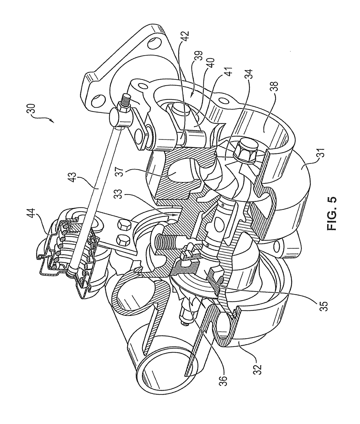
BACKGROUND OF THE INVENTIONField of the Invention[0001]The invention relates to an actuation device, in particular in the form of an electronic actuator.DESCRIPTION OF THE RELATED ART[0002]Such actuation devices are used for example in exhaust-gas turbochargers in order to open and close wastegate flaps. The actuation shank of such actuation devices may warm up owing to high ambient temperatures, such as for example in an engine bay, which firstly can adversely affect the actuation shank itself and secondly can result in an introduction of heat into the housing of the actuation device as a result of heat conduction via the actuation shank.[0003]It is therefore an object of the present invention to provide an actuation device which makes it possible for the actuation shank of the actuation device to be protected against adverse effects of heat.BRIEF SUMMARY OF THE INVENTION[0004]This object is achieved by the features of claim 1.[0005]The shielding cap of the actuation device accordi...

Claims


Application Information

Patent Timeline
Patent Type & Authority Patents(United States)
IPC IPC(8): F02B37/18F04D27/00F04D17/12H01F7/129
CPCF02B37/186F04D17/122H01F7/129F04D27/009Y02T10/144Y02T10/12
Inventor KRAEMER, JOCHENFETZER, HANS-JOERG
Owner BORGWARNER INC
Learn More