
Circuits and methods for using a high impedance, thin, coin-cell type battery in an implantable electroacupuncture device

a high-impedance, coin-cell-type battery technology, applied in the field of circuits and methods for using a high-impedance coin-cell-type battery in an implantable electroacupuncture device, can solve the problems of limited power output capacity of such batteries, relatively high output impedance, and inability to power any type of electronic circuit, so as to prevent the battery voltage, increase the battery voltage, and ensure the effect of operation

Active Publication Date: 2017-11-28
VALENCIA BIOSCIENCE INC
View PDF70 Cites 2 Cited by
  • Summary
  • Abstract
  • Description
  • Claims
  • Application Information

AI Technical Summary

Benefits of technology

[0023]The primary battery contained within the device housing and electrically coupled to the battery control circuitry has, in one embodiment, a nominal output voltage of 3 volts, and an internal battery impedance that is at least 5 ohms, and may be as high as 150 ohms or more. Advantageously, this battery control circuitry controls the value of the instantaneous surge current that may be drawn from the battery in order to prevent any large drops in the battery output voltage. Avoiding large drops in the battery output voltage assures that the circuits within the device will continue to operate as designed without failure. Being able to use a primary battery that has a relatively high internal impedance allows the battery to be thinner, and thus allows the device to be thinner and more easily implanted. The higher internal impedance also opens the door to using relatively inexpensive commercially-available coin-cell type batteries as the primary battery within the device, thereby greatly enhancing the manufacturability of the device and significantly lowering its cost.
[0028]Another characterization of the invention described herein is that of a method of operating an implantable electroacupuncture device (IEAD) that is powered only by a thin, coin-cell type battery having an internal impedance greater than 5 ohms, over a period of at least 2 years. The IEAD is designed to generate stimulation pulses during a stimulation session. The method comprises: (a) powering pulse generation circuitry within the IEAD with the coin-cell type battery; (b) limiting the duration of stimulation sessions during which stimulus pulses are generated to a time period that has a duty cycle of less than 0.05, where the duty cycle is the ratio of T3 to T4, where T3 is the duration of the stimulation session, and where T4 is the time interval between stimulation sessions; (c) boosting the battery voltage from the coin-cell type battery using a boost converter circuit by a factor of at least 4 in order to provide sufficient operating power to generate current stimulus pulses of up to 25 mA during a stimulation session; and (d) limiting the instantaneous current that can be drawn from the coin-cell type battery to prevent the battery voltage, VBAT, from dropping below safe operating levels.

Problems solved by technology

However, the power output capacity of such batteries is still severely limited.
That is, such enhanced batteries are still not capable of powering any type of electronic circuit where the instantaneous output current drawn from the battery—needed to power the circuit so that it can reliably perform its intended function—must be more than a few milliamps for more than a second or two.
The problem inherent in coin-cell type batteries, including the enhanced coin-cell batteries employing lithium-based chemistry, is that they have a relatively high output impedance, often as high as 100 to 200 ohms.
Such a dramatic drop in battery voltage could easily cause the circuit(s) powered by the coin-cell battery to malfunction.
For an implantable medical device—where reliable operation of the device is critical for the efficacy of the device as well as the safety of the patient within whom the device is implanted—such a 20% drop in battery voltage is not acceptable.
However, such custom-made batteries tend to be quite large and very expensive.
Thus, it is seen that because coin-cell batteries inherently have a high battery impedance—on the order of 100 to 200 ohms—they have never been considered for use in implantable medical devices, except perhaps extremely simple applications, such as monitoring internal body temperature, where the current demands placed on the battery are very low, e.g., less than 100 microamperes (0.1 ma).
The methods and devices disclosed in these patents, however, typically utilize (i) large implantable stimulators having long leads that must be tunneled through tissue over an extended distance to reach the desired stimulation site, (ii) external devices that must interface with implanted electrodes via percutaneous leads or wires passing through the skin, or (iii) inefficient and power-consuming wireless transmission schemes.
Such devices and methods are still far too invasive, or are ineffective, and thus are subject to the same limitations and concerns, as are the previously described electrical stimulation devices.
These operating commands allow limited external control of the device, such as ON / OFF and stimulation pulse amplitude adjustment.

Method used


Image

  • Circuits and methods for using a high impedance, thin, coin-cell type battery in an implantable electroacupuncture device
  • Circuits and methods for using a high impedance, thin, coin-cell type battery in an implantable electroacupuncture device
  • Circuits and methods for using a high impedance, thin, coin-cell type battery in an implantable electroacupuncture device

Examples


Embodiment Construction

Overview

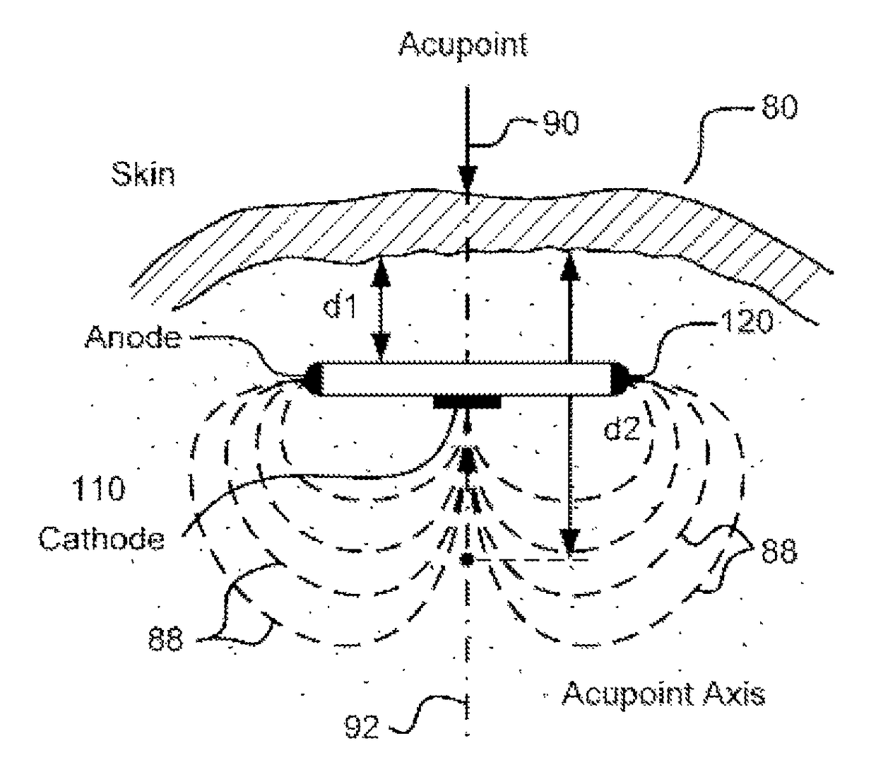
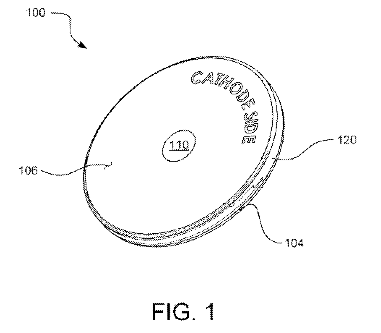
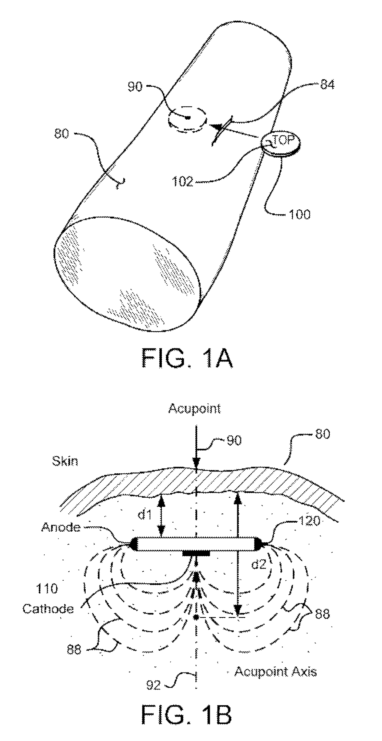
[0067]Disclosed and claimed herein is an implantable, self-contained, electroacupuncture (EA) device that is powered by a small, thin, coin-cell type battery having an internal impedance of at least five ohms. While the device described is intended for, and is described for use as, an EA device, it should be noted that it may be used for other similar tissue stimulation applications. Moreover, while the preferred EA device is leadless, for some applications a short lead may be needed to correctly position the electrodes precisely at a desired stimulation site. In an exemplary embodiment, the EA device includes two electrode contacts mounted on or connected to the surface of its housing. The EA device is adapted to treat a particular disease or health condition of a patient. In one embodiment, the electrodes of the EA device are mounted on the surfaces of its housing and include a central cathode electrode on one side of the housing, and an annular anode electrode that surrou...


PUM


Abstract

An implantable electroacupuncture device (IEAD) treats a specified medical condition of a patient through application of electroacupuncture (EA) stimulation pulses applied substantially at or near a specified acupoint, its underlying nerves, or other target tissue location. The IEAD includes an IEAD housing having an electrode configuration thereon that includes at least two electrodes, and pulse generation circuitry located within the IEAD housing and electrically coupled to the at least two electrodes. The pulse generation circuitry is adapted to deliver stimulation pulses to the patient's body tissue at or near the target tissue location in accordance with a specified stimulation regimen, the stimulation regimen requiring that the stimulation session have a duration of T3 minutes and a rate of occurrence of once every T4 minutes, and wherein a ratio of T3 / T4 is no greater than 0.05.

Description

RELATED APPLICATIONS[0001]The present application is a divisional application of U.S. patent application Ser. No. 13 / 769,699, filed Feb. 8, 2013, which application is a continuation-in-part application of U.S. patent application Ser. No. 13 / 598,582, filed Aug. 29, 2012 and issued as U.S. Pat. No. 8,965,511. U.S. patent application Ser. No. 13 / 769,699 also claims priority under 35 U.S.C. §119(e) to U.S. Provisional Patent Application No. 61 / 609,875, filed Mar. 12, 2012; U.S. Provisional Patent Application No. 61 / 672,257, filed Jul. 16, 2012; U.S. Provisional Patent Application No. 61 / 672,661, filed Jul. 17, 2012; U.S. Provisional Patent Application No. 61 / 673,254, filed Jul. 19, 2012; and U.S. Provisional Patent Application No. 61 / 674,691, filed Jul. 23, 2012. All of these applications are incorporated herein by reference in their respective entireties.BACKGROUND INFORMATION[0002]Coin-cell type batteries are known in the art. They can be used for just about any electronic device or c...

Claims


Application Information

Patent Timeline
Patent Type & Authority Patents(United States)
IPC IPC(8): A61N1/36A61H39/00A61N1/378A61N1/375A61N1/372
CPCA61N1/378A61H39/002A61N1/36125A61N1/36175A61N1/3756A61N1/3782A61N1/37205A61N1/3758A61H2201/5005A61H2201/5035A61H2201/5038A61H2201/5097A61N1/36117
Inventor PETERSON, DAVID K. L.GREINER, JEFFREY H.
Owner VALENCIA BIOSCIENCE INC
Learn More