
Underwater acoustic beacon location system

a technology of acoustic beacon and location system, which is applied in the field of underwater acoustic beacon location system, can solve the problems of system not providing a signal gain or a greater detection range than can be achieved, system needed for the method requires potentially expensive modifications not only to the beacon, and achieves the effect of precise estimation

Active Publication Date: 2017-11-28
UNITED STATES OF AMERICA
View PDF2 Cites 17 Cited by
  • Summary
  • Abstract
  • Description
  • Claims
  • Application Information

AI Technical Summary

Benefits of technology

The present invention provides a method of using a linear acoustic sensor array to accurately locate a ULB during a single pass of a search pattern. The technical effect of this invention is to improve the accuracy of location estimation for ULBs.

Problems solved by technology

While use of the system provides an improved location estimate relative to that provided by a single hydrophone; the system does not provide a signal gain or a greater detection range than can be achieved by using an array of spatially distributed sensors.
This would be a considerable expense.
While this method may improve the probability of locating a downed aircraft; the system needed for the method requires potentially expensive modifications not only to the beacon, but to the downed aircraft was well.
Also, it is unknown how reliable the proposed beacon deployment and tethering method would be in a real world environment.
While the method facilitates data recovery by eliminating the requirement of physical access to the aircraft debris field on the seafloor; the method does not provide an advantage for detecting and locating the aircraft data recorder in a first instance.
The data recovery method would also require widespread and costly changes to commercial airliners.
While various attempts have been made to resolve the problem of detecting and locating a ULB on the seafloor; the proposed improvements require costly and widespread modifications.

Method used


Image

  • Underwater acoustic beacon location system
  • Underwater acoustic beacon location system
  • Underwater acoustic beacon location system

Examples


Embodiment Construction

[0032]A known passive sonar equation is used to estimate the maximum distance at which an underwater tow body is likely to detect an acoustic signal transmitted by the Underwater Location Beacon (ULB). The Figure of Merit (FOM) equation for a passive sonar detection system is defined as the maximum attenuation in the acoustic intensity of the transmitted signal that can occur for successful detection of the transmitted signal. The FOM is determined in decibels as

FOM=SL−NL+DI−DT  (1)

where “SL” is the source level of the ULB signal in decibels referenced to one micro-pascal at one meter from the acoustic center of an acoustic transducer (dB re 1 uPa@m); “NL” is the spectrum level of interfering noise in decibels referenced to one micro-pascal squared in a one hertz band (dB re 1 uPa2 / Hz), “DI” is the directivity index of the acoustic sensor in decibels and “DT” is the detection threshold of the acoustic sensor in decibels.

[0033]Sonar performance parameters that can apply in a search f...


PUM


Abstract

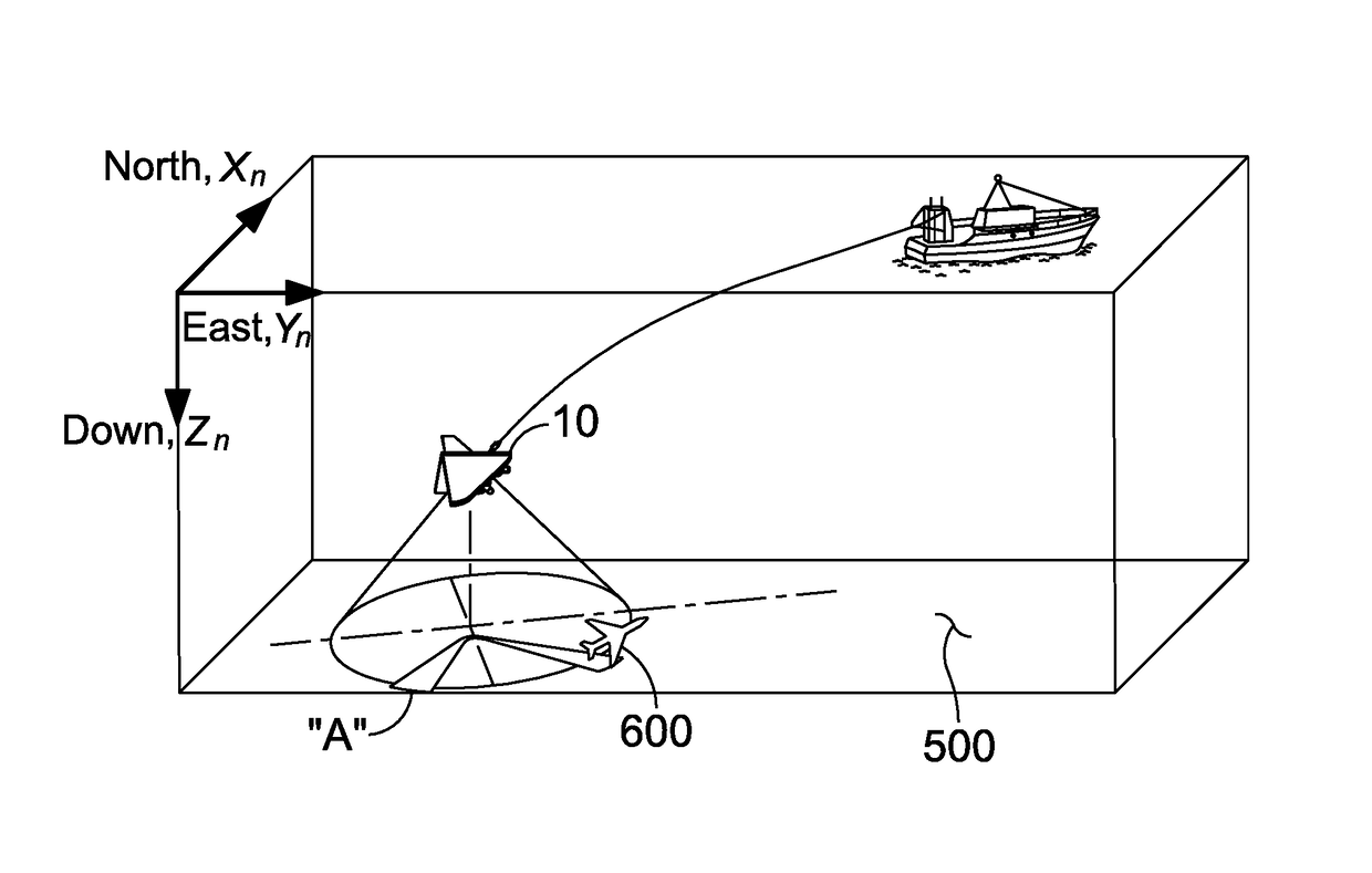
A method using a tow body and sensor array for locating an underwater location beacon is provided. The steps of the method are moving the body and array in a direction of motion; orientating the array orthogonal to the direction of motion; beamforming acoustic conical beams from the array onto a seafloor; detecting a time series of acoustic data channels from the beacon; converting the data channels into spatial beams of acoustic frequency; determining if a signal of the underwater location beacon is present from each spatial beam; calculating likelihood functions for locations of the beacon to represent an area of the seafloor from which the signal of the underwater location beacon is to have originated; accumulating likelihood functions for the location of the underwater location beacon over the course of a search pattern; and producing a grid for a beacon location based on the likelihood functions.

Description

[0001]The present application claims the benefit of U.S. Provisional Application Ser. No. 62 / 297,179 filed on Feb. 19, 2016 by the inventor, Steven E. Crocker and entitled “Underwater Acoustic Beacon”.STATEMENT OF GOVERNMENT INTEREST[0002]The invention described herein may be manufactured and used by or for the Government of the United States of America for governmental purposes without the payment of any royalties thereon or therefor.CROSS REFERENCE TO OTHER PATENT APPLICATIONS[0003]None.BACKGROUND OF THE INVENTION(1) Field of the Invention[0004]An acoustic detection system is provided in which the detection system can search for and can locate an underwater location beacon.(2) Description of the Prior Art[0005]Various methods of detecting, locating and recovering an Underwater Location Beacon (ULB) have been proposed. Methods for locating a ULB include cross-correlating acoustic signals received by two or more hydrophones in which the hydrophones are separated at a discernable dis...

Claims


Application Information

Patent Timeline
Patent Type & Authority Patents(United States)
IPC IPC(8): G01S15/18G01S5/18
CPCG01S5/183G01S5/18G01S5/20
Inventor CROCKER, STEVEN E
Owner UNITED STATES OF AMERICA
Learn More