
Multi-phase linear motor with continuously wound coils in each phase

a linear motor and continuous wound technology, applied in the field of linear motors, can solve the problems of reducing the wiring efficiency of arranging, reducing the size of the armature, and increasing the width of the armature, so as to reduce the number of connection points to the circuit board, reduce the size of the armature, and minimize the wiring work of the jumper wire between the coils

Active Publication Date: 2017-12-05
SANYO DENKI CO LTD
View PDF15 Cites 0 Cited by
  • Summary
  • Abstract
  • Description
  • Claims
  • Application Information

AI Technical Summary

Benefits of technology

The present invention improves the wiring work efficiency and reduces the size of a linear motor by arranging the lead of each phase and the ground wire effectively. The coils of the same phase group are continuously wound over the insulative bobbins, minimizing the wiring work of the jumper wire between the coils. The tap conductor, the jumper wire, and the terminal wire of the coils of a different phase group are separately disposed in the magnetic cover, effectively utilizing the corner portions which are dead spaces in the magnetic cover. Only the terminal of the insulated shielded wire of each phase is connected to the circuit board, reducing the number of connection points to the circuit board.

Problems solved by technology

Such a configuration increases the width of the armature, which is disadvantageous to reduction in size of the armature.
In this case the number of connection points to the circuit board is increased, which degrades the wiring work efficiency for arranging the lead of each phase and the ground wire.

Method used


Image

  • Multi-phase linear motor with continuously wound coils in each phase
  • Multi-phase linear motor with continuously wound coils in each phase
  • Multi-phase linear motor with continuously wound coils in each phase

Examples


first embodiment

[First Embodiment]

[Configuration of Linear Motor]

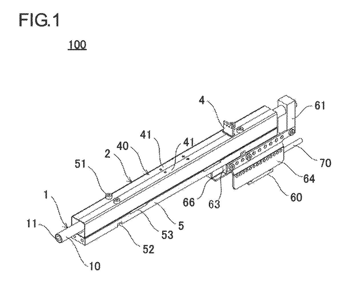
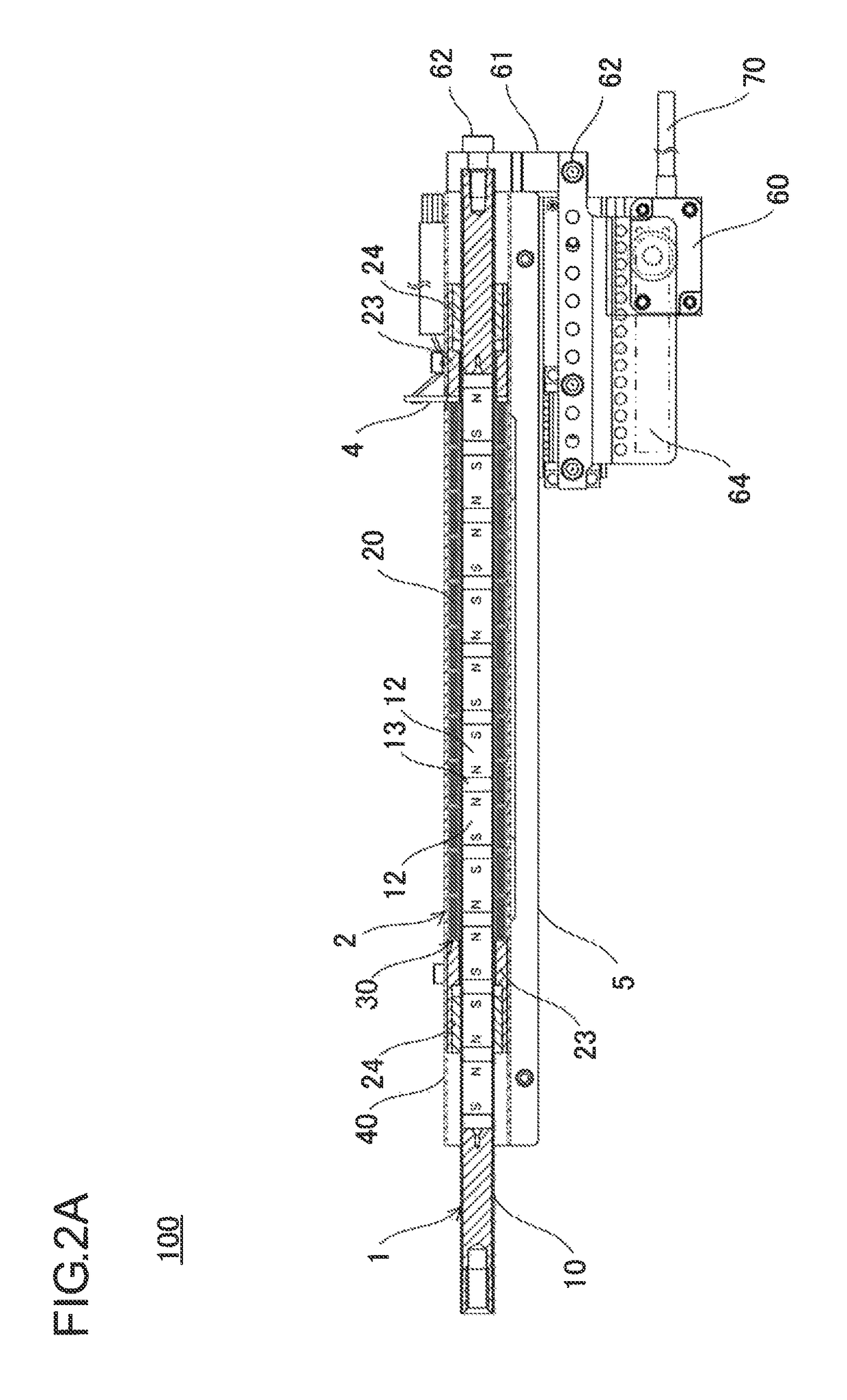
[0053]Referring first to FIGS. 1 through 9, the configuration of the linear motor according to the first embodiment will be described. FIG. 1 is a perspective view showing the linear motor according to the first embodiment. FIG. 2A is a vertical cross-sectional view showing the linear motor according to the first embodiment. FIG. 2B is a top view showing the linear motor according to the first embodiment. FIG. 2C is a bottom view showing the linear motor according to the first embodiment. FIG. 2D is a side view showing the distal side of the linear motor according to the first embodiment. FIG. 2E is a side view showing the proximal side of the linear motor according to the first embodiment.

[0054]As shown in FIG. 1, the linear motor 100 according to the first embodiment includes an excitation unit 1, an armature 2, a circuit board 4, and a frame 5.

[0055]The excitation unit 1 includes a shaft 10 and a plurality of permanent magnets 12, ...

second embodiment

[Second Embodiment]

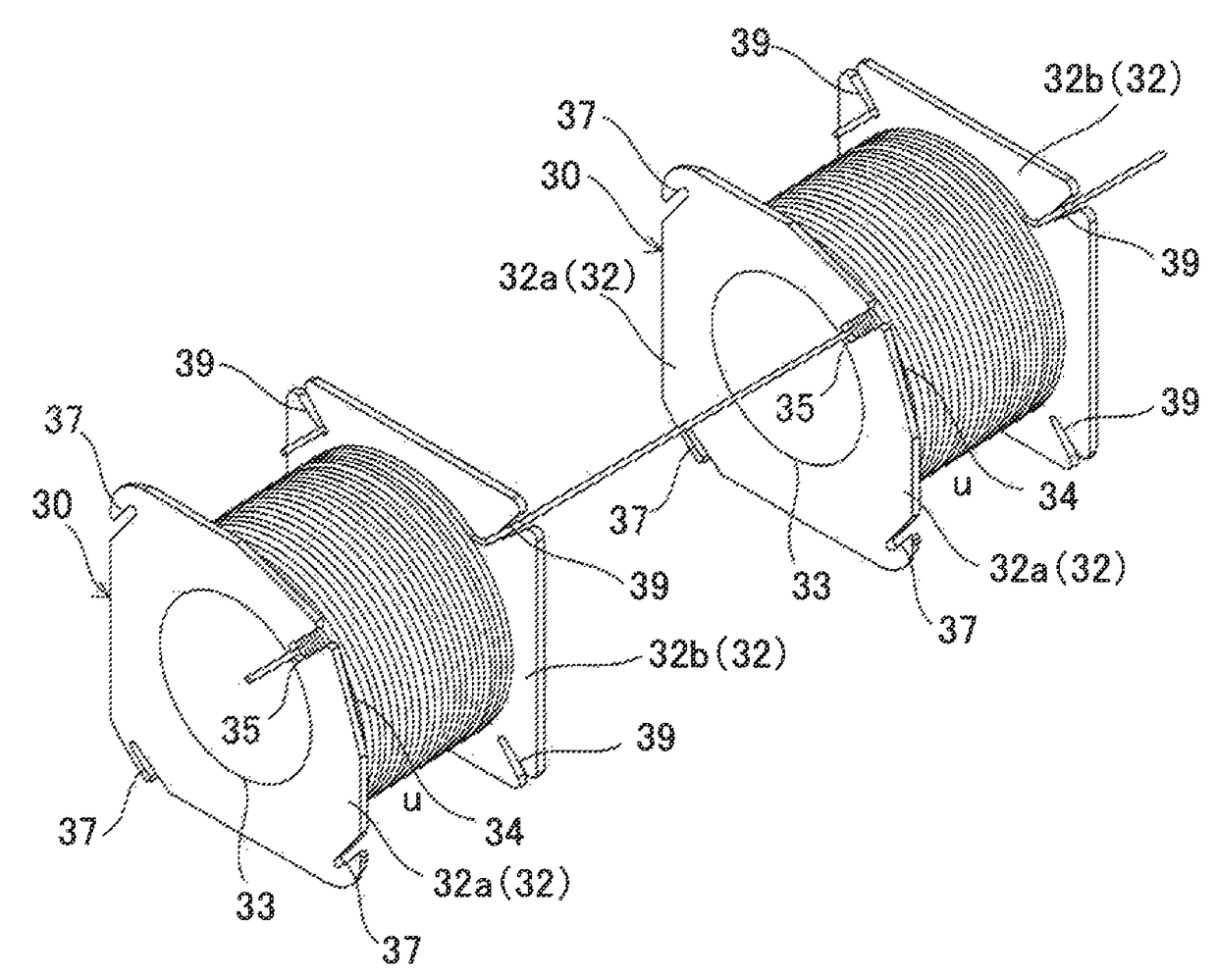
[0118]Referring now to FIGS. 10A to 10C, a linear motor according to a second embodiment will be described. FIG. 10A is a perspective view showing a bobbin according to the second embodiment. FIG. 10B is a side view showing the distal side of the bobbin according to the second embodiment. FIG. 10C is a side view showing the proximal side of the bobbin according to the second embodiment.

[0119]As shown in FIGS. 10A to 10C, the linear motor according to the second embodiment is configured similarly to the first embodiment, except for the structure of a bobbin 230 around which the coil is to be wound.

[0120]More specifically, the linear motor according to the second embodiment is different from the first embodiment in the shape of flange portions 232 of the bobbin 230. A distal side flange portion 232a and a proximal side flange portion 232b are different in shape from each other.

[0121]The distal side flange portion 232a is an annular plate-shaped member including a ci...

third embodiment

[Third Embodiment]

[0128]Referring now to FIGS. 11A to 11D, a linear motor according to a third embodiment will be described. FIG. 11A is a perspective view showing a bobbin according to the third embodiment. FIG. 11B is a side view showing the distal side of the bobbin according to the third embodiment. FIG. 11C is a side view showing the bobbin according to the third embodiment. FIG. 11D is a side view showing the proximal side of the bobbin according to the third embodiment.

[0129]As shown in FIGS. 11A to 11D, the linear motor according to the third embodiment is configured similarly to the first embodiment, except for the structure of a bobbin 330, which is a variation of the bobbin according to the second embodiment.

[0130]More specifically, the linear motor according to the third embodiment is different from the second embodiment in the configuration of flange portions 332 of the bobbin 330. A distal side flange portion 332a and a proximal side flange portion 332b have generally ...


PUM


Abstract

A linear motor includes an excitation unit including a shaft and a plurality of permanent magnets located in the shaft, and an armature including a plurality of coils surrounding the excitation unit and a magnetic cover covering the coils. The plurality of coils of the same phase group are continuously wound over a plurality of insulative bobbins. A tap conductor, a jumper wire between the coils, and a terminal wire of the coils in different phase groups that are continuously wound are separately disposed in different corner portions in the magnetic cover, and the terminal wire of each phase is connected to a circuit board.

Description

CROSS-REFERENCE TO RELATED APPLICATIONS[0001]This application claims priority to Japanese Application No. 2013-197463, filed Sep.24, 2013.BACKGROUND[0002]1. Technical Field[0003]The present invention relates to a linear motor that gives a linear thrust to an object to be driven, utilizing electromagnetic induction.[0004]2. Description of Related Art[0005]A rod-type linear motor includes a rod with permanent magnets, and coils surrounding the rod, and gives a thrust force to the rod in the axial direction thereof utilizing electromagnetic induction arising from the magnetic field of the permanent magnets and current running on the coils.[0006]The rod-type linear motor can be easily built in a small size, yet exhibits high performance because of the advantages such as simple structure and small cogging force from fluctuation of the magnetic flux. The rod-type linear motor is employed, for example, in a chip mounter of semiconductor manufacturing equipment.[0007]In the aspect of the ar...

Claims


Application Information

Patent Timeline
Patent Type & Authority Patents(United States)
IPC IPC(8): H02K41/02H02K5/02H02K3/28H02K9/02H02K3/47H02K41/03
CPCH02K41/02H02K3/28H02K3/47H02K9/02H02K41/031H02K5/02Y02T10/641Y02T10/64
Inventor TANG, YUQIMATSUSHITA, TAKASHI
Owner SANYO DENKI CO LTD
Learn More