Fluid bed classification elements

a technology of fluid bed and classification elements, which is applied in the direction of gas current separation, solid separation, pneumatic table, etc., can solve the problems of inability to give the expected effect, clogging of physical restrictions inside the granulator, and difficulty in physical screening through meshes, screens, etc., and has been seen as impractical and energy-intensiv

Inactive Publication Date: 2017-12-12
BEXO AS
View PDF33 Cites 3 Cited by
  • Summary
  • Abstract
  • Description
  • Claims
  • Application Information

AI Technical Summary

Benefits of technology

[0028]In an embodiment of the above classifying fluid bed granulation unit, the element constitutes a partial or full separation wall in the fluid bed granulation unit, and the upper and lower side slots are located at opposite sides of each channel so that the upper and lower slots are located at opposite sides of the separation wall, respectively, to make it possible through the upper slots to take out the larger particles at one side of the separation wall and through the lower slots to take out the smaller particles at the opposite side of the separation wall.

Problems solved by technology

Internal screening by physical means of a mesh, screen, slots etc. is difficult when the desired effect is to retain the smallest particles and moving the biggest particles towards the outlet.
Physical restrictions inside the granulator are also clogging quickly due to the plasticity and stickiness of the particles.
All of these methods have failed to give the expected effect or have been seen as impractical and energy intensive.
This effect however is found not to be sufficient for eliminating the external screening and crushing loop.
Any separation outside the high-density phase has the inherent disadvantage of external screening where the smallest particles have to be brought back to the inlet side.
The disadvantage is however that the bed has to be fully redesigned, and that the claimed classification effect will be disturbed by the bubble formation and effect of the spraying nozzles in each compartment.
The limit to inclination and position of the baffles and compartments are reducing the claimed effect in practical beds.
The way the baffles are installed, is not giving a consistent effect.
The small particles on the slow side of the baffle is also prone to moving towards the outlet at the bottom of the bed, and the larger particles on the fast side of the baffle will inevitably also follow the backward direction towards the inlet side.
The classification effect is however not significant enough to eliminate the external screening, crushing and recycling loop.

Method used


Image

  • Fluid bed classification elements
  • Fluid bed classification elements
  • Fluid bed classification elements

Examples


Embodiment Construction

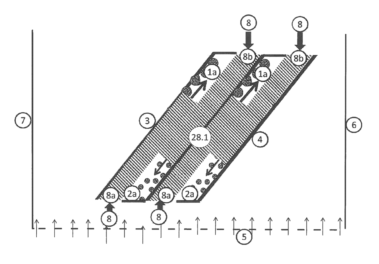
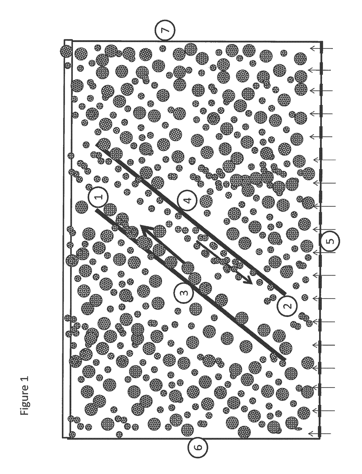
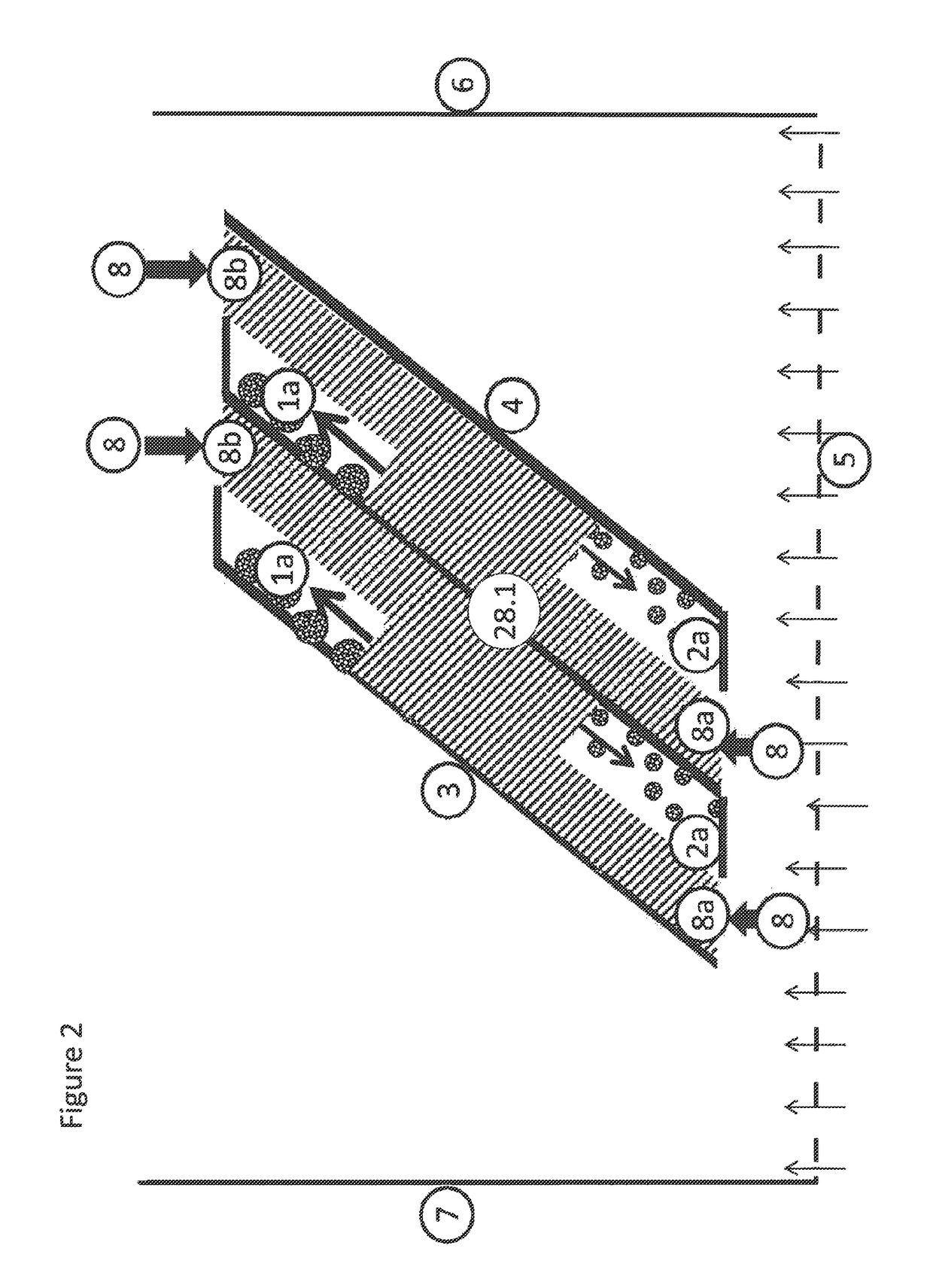
[0057]The present invention relates to a classifying fluid bed granulation unit comprising in the fluid bed section thereof at least one particle classification element comprising one or more vertically inclined channels having top and bottom end feed openings, and wherein the one or more vertically inclined channels have upper and lower side slots.

[0058]In an aspect, the classifying fluid bed granulation unit comprises: a perforated bed floor; a fluid bed section; a solid feed inlet; a fluidization air inlet; a liquid solution or melt feed inlet and nozzles; an air outlet; and a product outlet. Said fluid bed section comprises at least one particle classification element comprising one or more vertically inclined channels having top and bottom end feed openings, and wherein the one or more vertically inclined channels have upper and lower side slots.

[0059]In another aspect, the classifying fluid bed granulation unit comprises: a perforated bed floor; a fluid bed section; an interna...


PUM

PropertyMeasurementUnit
lengthaaaaaaaaaa
lengthaaaaaaaaaa
lengthaaaaaaaaaa

Abstract

A classifying fluid bed granulation unit includes a perforated bed floor; a fluid bed section; a solid feed inlet or internal crushing device; a fluidization air inlet; a liquid solution or melt feed inlet and nozzles; an air outlet; and a product outlet; wherein the fluid bed section comprises at least one particle classification element comprising one or more vertically inclined channels having top and bottom end feed openings, and wherein the one or more vertically inclined channels have upper and lower side slots. In operation of the above fluid bed granulation unit, each channel of the element is separating particles into large particle and small particle fractions and transporting the large particle fraction upwards and the small particle fraction downwards in each channel, and the large particle and small particle fractions are transported out of the upper and lower side slots, respectively.

Description

TECHNICAL FIELD[0001]The present invention relates to a classifying fluid bed granulation unit comprising in the fluid bed section at least one particle classification element, and a method for classifying granules or particles of different size inside an operating fluid bed. The method comprises the use of classifying elements which are placed in the fluid bed without restricting or obstructing the other functions of the bed. The classifying elements are using the physical differences in flow and fluidization characteristics for particles of different size to sort and transport the particles between compartments and along the walls of the bed. The method is applicable for processes using fluidization as a medium in granulation, agglomeration, accretion, aggregation or other forms of particle growth. The method is also applicable for processes which include fluidization and particle reduction or crushing.BACKGROUND OF THE INVENTION[0002]In the granulation processes where particle gr...

Claims


Application Information

Patent Timeline
Patent Type & Authority Patents(United States)
IPC IPC(8): B07B4/08B01J2/16B01J8/24B03B4/00B01J8/18
CPCB01J2/16B01J8/1872B01J8/24B07B4/08B03B4/00B01J2208/00938B01J2208/0084B01J2208/00672
Inventor INGELS, RUNE
Owner BEXO AS
Why Eureka
Try Eureka