Fastener assembly and system for manufacturing the same

a technology of fasteners and assembly systems, applied in the field of plastic fasteners, can solve the problems of insufficient secure use of pressure-sensitive adhesives to apply paper-based labels to the paddles of corresponding plastic fasteners, difficult to integrate the in-line label applicator into the continuous molding process in an efficient manner, and high risk of tampering, etc., to achieve efficient and reliable operation, rapid and inexpensive manner, and low cost

Active Publication Date: 2017-12-12
AVERY DENNISON CORP
View PDF18 Cites 1 Cited by
  • Summary
  • Abstract
  • Description
  • Claims
  • Application Information

AI Technical Summary

Benefits of technology

[0020]It is yet another object of the present invention to provide a fastener of the type described above that displays identifying information in the fastener paddle in order to, inter alia, improve brand recognition, enhance marketability and deter ticket-switching.
[0023]It is another object of the present invention to provide a fastener manufacturing system of the type described above that allows for customized modification of the identifying information provided in each paddle in a rapid and inexpensive manner. It is yet another object of the present invention to provide a fastener manufacturing system as described above which has a limited number of parts, which is inexpensive to implement, which is efficient and reliable in its operation and which is easy to use.

Problems solved by technology

As a first shortcoming, it has been found that the use of a pressure-sensitive adhesive to apply a paper-based label onto the paddle of a corresponding plastic fastener is not adequately secure.
As a result, plastic fasteners with paper-labels adhesively bonded thereto are highly susceptible to tampering.
As a second shortcoming, it has been found to be difficult to integrate the in-line label applicator into the continuous molding process in an efficient manner.
In particular, the precision and timing that is required between the label applicator and in-line transfer of the strip of fasteners away from the continuous mold wheel is considered too difficult to implement in a high-speed environment, thereby limiting product output.
As a third shortcoming, the aforementioned process is only capable of producing plastic fasteners with identifying information on one side of its enlarged paddle.
As a result, the aforementioned process is both costly to implement and unable to support any rapid, on-the-fly modification (i.e., customization) of the information displayed on the fastener paddles.

Method used


Image

  • Fastener assembly and system for manufacturing the same
  • Fastener assembly and system for manufacturing the same
  • Fastener assembly and system for manufacturing the same

Examples


Embodiment Construction

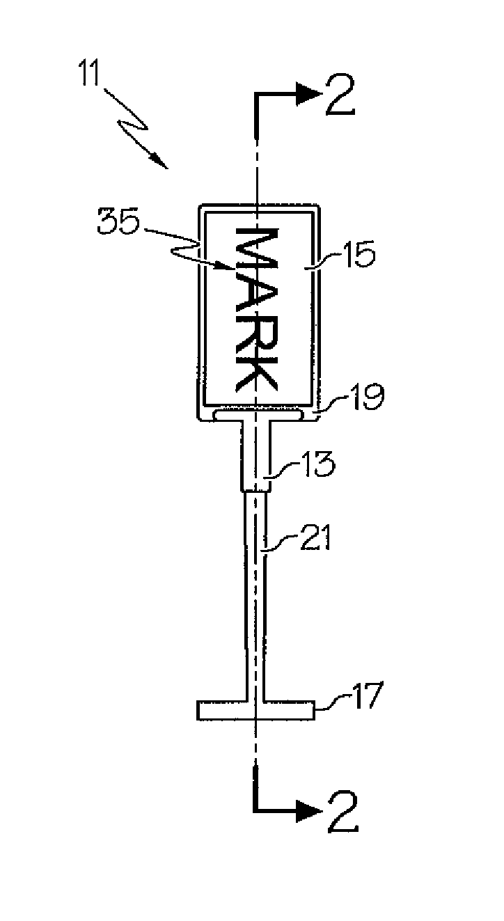
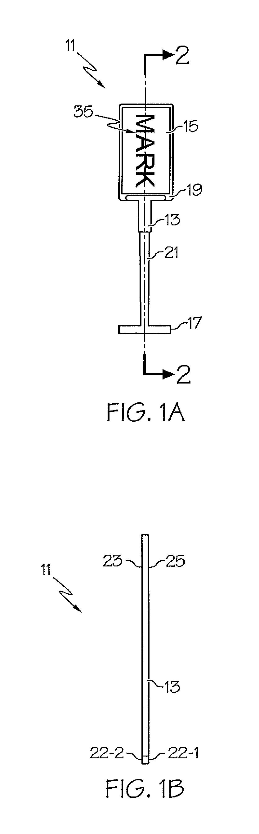
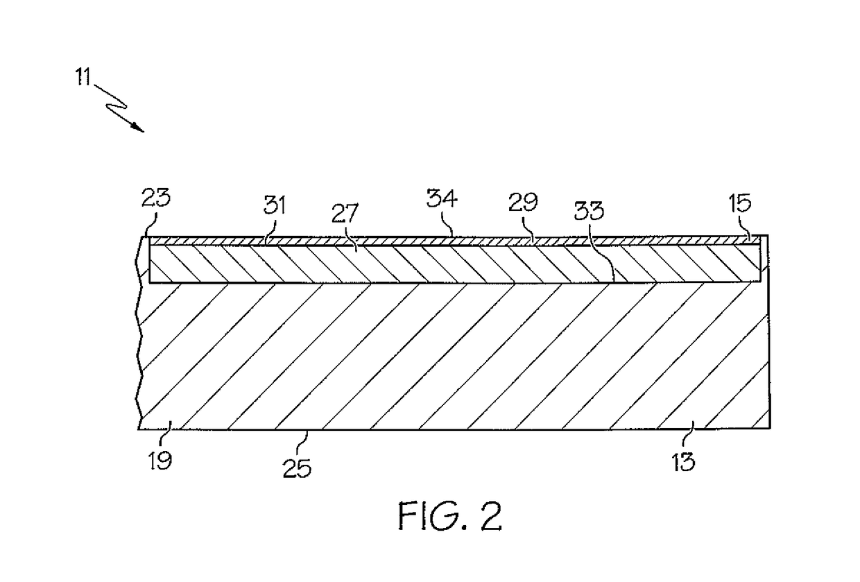
[0033]The apparatuses and methods disclosed in this document are described in detail by way of examples and with reference to the figures. Unless otherwise specified, like numbers in the figures indicate references to the same, similar, or corresponding elements throughout the figures. It will be appreciated that modifications to disclosed and described examples, arrangements, configurations, components, elements, apparatuses, methods, materials, etc. can be made and may be desired for a specific application. In this disclosure, any identification of specific shapes, materials, techniques, arrangements, etc. are either related to a specific example presented or are merely a general description of such a shape, material, technique, arrangement, etc. Identifications of specific details or examples are not intended to be, and should not be, construed as mandatory or limiting unless specifically designated as such. Selected examples of apparatuses and methods are hereinafter disclosed a...


PUM

PropertyMeasurementUnit
thicknessaaaaaaaaaa
widthaaaaaaaaaa
lengthaaaaaaaaaa

Abstract

A fastener assembly includes a molded plastic fastener shaped to define a filament, a paddle at one end of the filament, and a cross-bar at the other end of the filament. The fastener assembly additionally includes a printed label embedded in the paddle, the printed label including an electrically chargeable, stiffness enhancing laminate that is applied to a print receptive polymer substrate. An in-line system for manufacturing a continuously connected supply of the fastener assemblies includes a rotatable mold wheel, a feed mechanism for advancing a continuous, ionized, printed polymer web in a near tangential relationship relative to the mold wheel periphery, a cutting mechanism for transversely cutting through the web to form a plurality of rectangular printed labels that are magnetically drawn into corresponding cavities in the mold wheel, an extruder for applying molten plastic into the cavities and a knife for skiving excess hardened plastic from the mold wheel periphery.

Description

CROSS-REFERENCE TO RELATED APPLICATION(S)[0001]None.FIELD OF THE INVENTION[0002]The present invention is in the field of devices used for branding, advertising, marketing and providing information to consumer goods.BACKGROUND OF THE INVENTION[0003]The present invention relates generally to plastic fasteners of the type used to attach merchandise tags to pieces of fabric.[0004]Plastic fasteners of the type used to attach merchandise tags to pieces of fabric, such as articles of clothing, product labels, and the like, are well known in the art and widely used in the retail industry. Typically, such fasteners comprise an elongated plastic member having a first end shaped to define a cross-bar (also commonly referred to as a “T-bar”), a second end shaped to define a paddle, and a thin filament portion interconnecting the cross-bar and the paddle. As will be described further below, the cross-bar is adapted to be inserted first through a tag and then into a desired piece of fabric, with ...

Claims


Application Information

Patent Timeline
Patent Type & Authority Patents(United States)
IPC IPC(8): G09F3/12B29C47/00B29C47/02B29C48/05B29C48/154
CPCG09F3/12B29C47/025B29C47/0066B29C47/0014B29C48/05B29C48/0022B29C48/154
Inventor BUROUT, CHARLESSHILALE, THOMAS
Owner AVERY DENNISON CORP
Why Eureka
Try Eureka