Improved structure of forging machine tool C-shaped body

A technology for forging machine tools and fuselages, which is applied in the field of C-shaped fuselage structures, can solve problems such as increased manufacturing costs, uneven front and rear gaps, and failure to apply, so as to improve performance and productivity, increase technical gold content, and expand market share. rate effect

Inactive Publication Date: 2011-05-11
刘世雄
View PDF16 Cites 1 Cited by
  • Summary
  • Abstract
  • Description
  • Claims
  • Application Information

AI Technical Summary

Problems solved by technology

[0004] 1. The accuracy of the press is reduced, making the front and rear gaps between the upper and lower dies uneven, δ 前 ≠δ 后 , so that the workpiece produces deviations and burrs, which reduces the accuracy of the workpiece;
[0005] 2. A horizontal side pressure is generated on the upper mold, which causes the upper mold and the lower mold to contact or even collide, which accelerates the wear and tear of the mold and even breaks it, reducing the life of the mold;
[0006] 3. Accelerated the wear of sliders and guide rails
[0007] Since the appearance of the open press at the end of the nineteenth century for more than a hundred years, people have discovered its defects and designed some improved structures, but they have not completely solved the problem:
[0009] 2. If figure 2 b. figure 2 The improved structure shown in c is to add a tie rod inside the fuselage, because the tie rod is behind the pressure centerline of the fuselage, so the effect of this is not obvious, and it will increase the manufacturing cost, so it has not been applied
However, the result of doing this is like figure 2 The structure shown in a is the same, and the operation is very inconvenient, which greatly weakens the superiority of the open press
[0012] Judging from the explanatory materials on the existing domestic and foreign open press product samples and semi-closed fuselage products, the angular deformation of the C-type fuselage still has an impact on its working performance (especially the mold life), in order to eliminate this Due to this influence, the semi-closed fuselage has to be adopted, which fully shows that the angular deformation problem of the current open press has not been completely solved.

Method used


Image

  • Improved structure of forging machine tool C-shaped body
  • Improved structure of forging machine tool C-shaped body
  • Improved structure of forging machine tool C-shaped body

Examples


Embodiment Construction

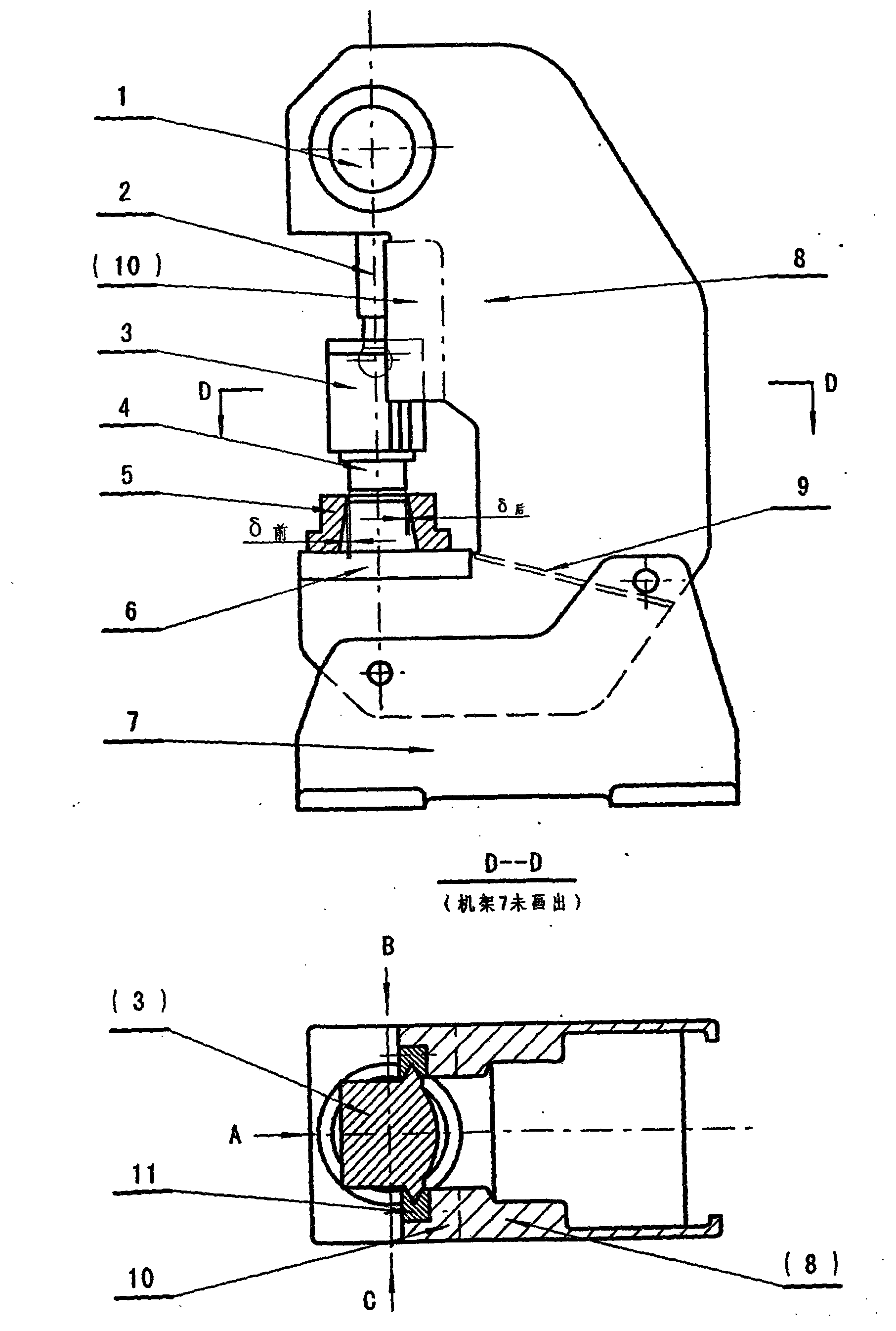
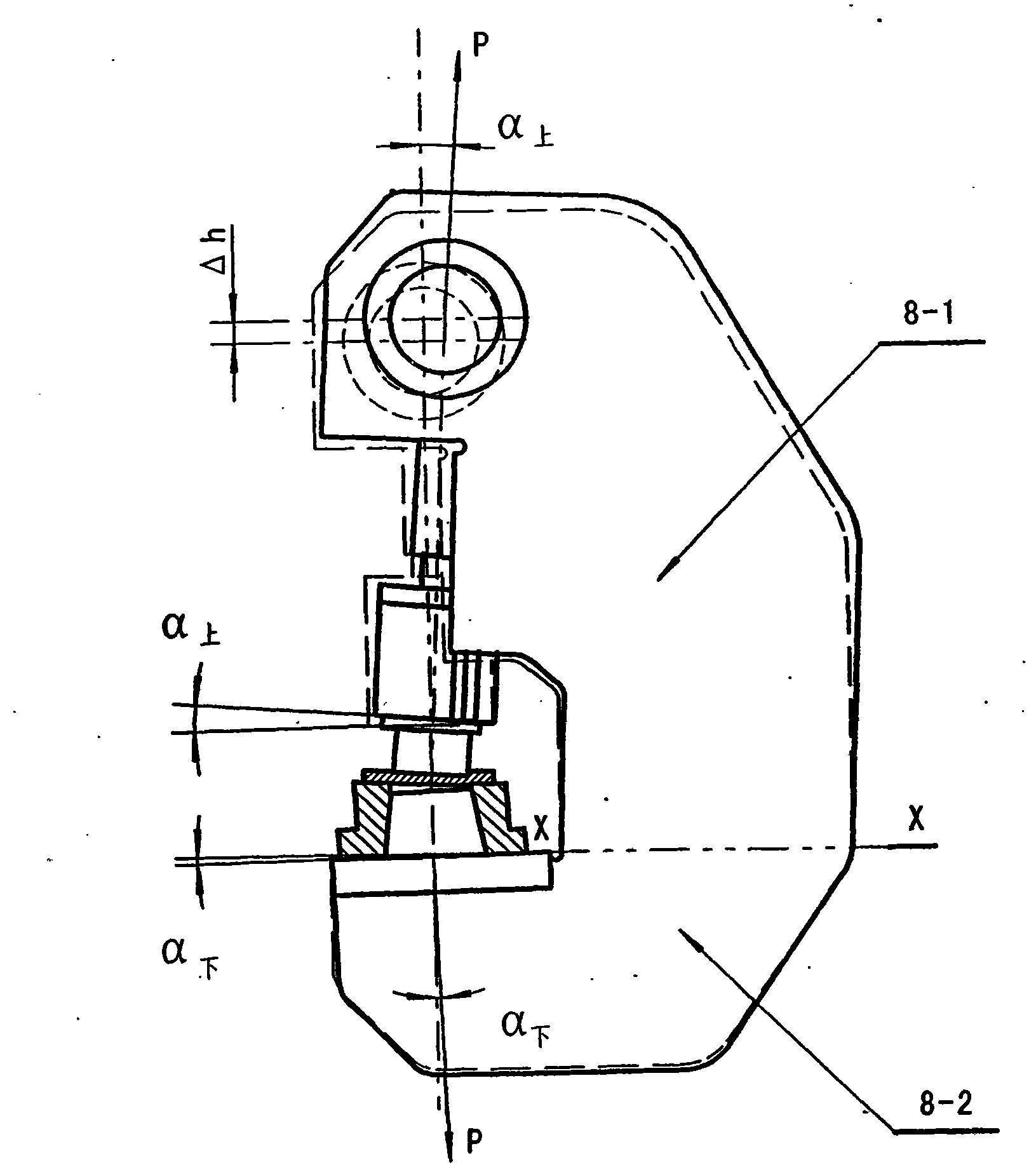
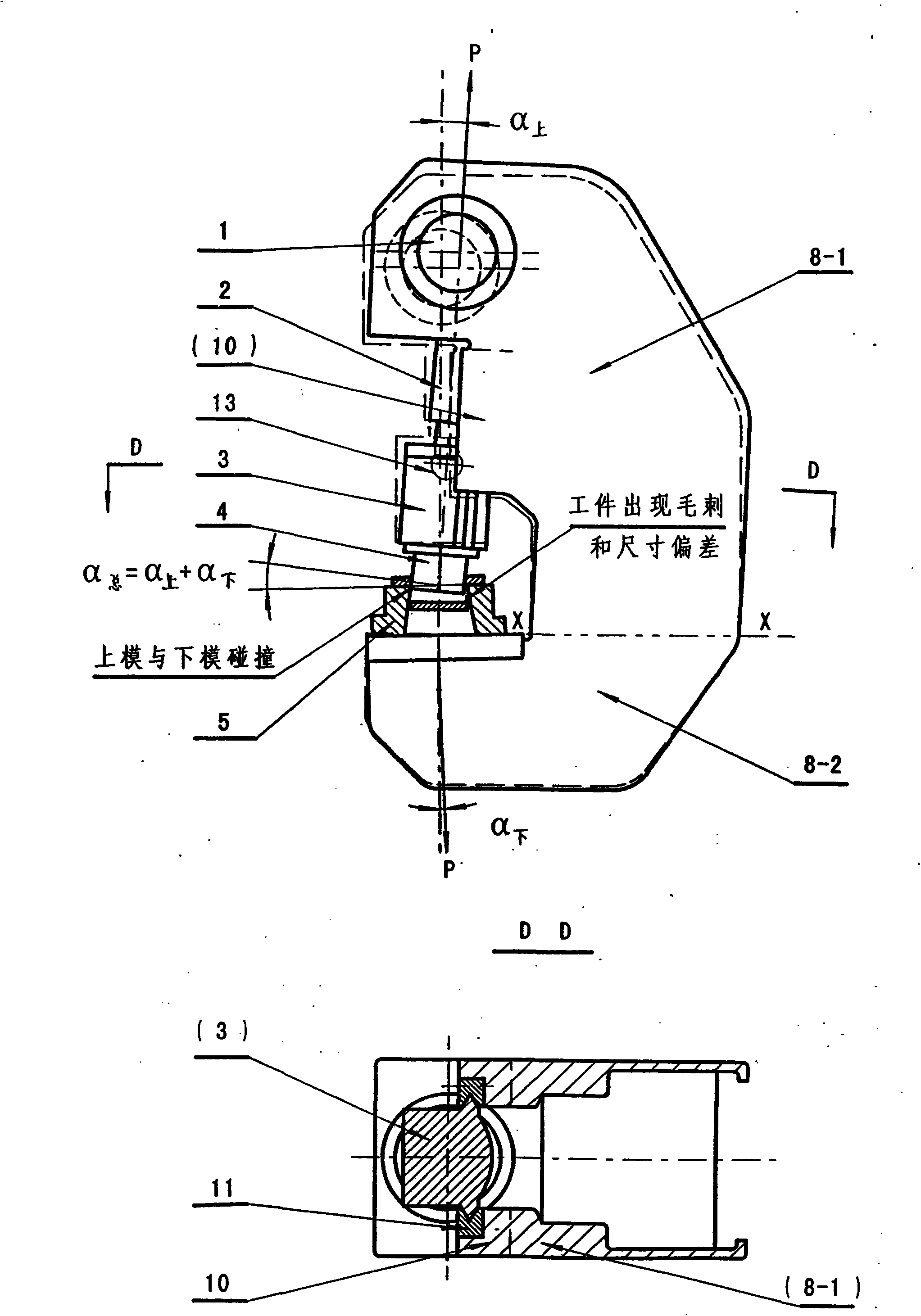
[0029] The first example Figure 4 with image 3 As shown, the part of the base [10] of the fixed rail [11] on the upper body [8-1] is separated from the upper body [8-1], and the separated base part [10] is on the upper part The outer side of the fuselage [8-1] extends backward and downward to form a support plate [12], and the support plate [12] is integrated with the side plate [14] of the lower fuselage [8-2]. In this way, when the open press is under working pressure, although the upper fuselage [8-1] will produce upward angular deformation α on , But because the base part [10] of the fixed guide rail [11] has been separated from the upper body [8-1], it will not drive the slider [3] and the upper mold [4] to undergo upward angular deformation α on ; Although the lower body [8-2] and the lower mold [5] will produce downward angular deformation α under , But at the same time it must also drive the side plate [14], support plate [12], base [10], guide rail [11] and slider [...


PUM


Abstract

A working mechanism cantilever consisting of a crank, a connecting rod and a sliding block, as well as an upper die and a lower die on an open type pressing machine can enter a working region from three directions in front of the C-shaped body, thus the great convenience is brought for the operator. But, the C-shaped structure causes the defects of poor rigidity of the machine body, especially large angular deformation, reduced accuracy, shortened service life of the dies and the sliding block as well as a guide rail, and the like. The invention is characterized in that a base part [10] for fixing the guide rail on an upper machine body [8-1] is separated from the upper machine body [8-1], the separated base part [10] extends backwards and downwards on the outer side of the upper machine body [8-1] to form a support plate [12], and the upper plate [12] and a side plate [14] of a lower machine body [8-2] are made into a whole. Therefore, when the open type pressing machine bears working pressure, the upper die can not generate angular deformation relative to the lower die, thus the defects are thoroughly eliminated. The invention can maintain the advantage of convenient operation of the open type pressing machine and has the advantage of high accuracy of a closed type pressing machine. Moreover, by the invention, the working property of the open type pressing machine can be improved and the manufacture cost of the open type pressing machine can be lowered.

Description

1. Technical Field [0001] The invention relates to a forging machine tool, particularly a C-shaped body structure of an open press. 2. Background technology [0002] Some of the forging machines have a C-shaped structure, and the most typical ones are Figure 1a The body of the open press (usually called a punch) shown in [8]. Composed of crank [1], connecting rod [2], slider [3], upper mold [4] mounted on the slider [3], and lower mold [5] mounted on the worktable [6] This working mechanism is cantilevered in front of the fuselage [8]. The operator can enter the working area from the front A and the left and right sides B and C. This is important for the assembly and disassembly and adjustment of the mold, and the feeding and taking out of the workpiece. , The adjustment of the gap between the guide rails and the installation and use of mechanized and automatic feeding devices have brought great convenience. Therefore, in terms of small and medium-sized presses, compared with th...

Claims


Application Information

Patent Timeline
Patent Type & Authority Applications(China)
IPC IPC(8): B21J13/04
Inventor 刘世雄
Owner 刘世雄
Why Eureka
Try Eureka