Eureka AIR delivers breakthrough ideas for toughest innovation challenges, trusted by R&D personnel around the world.

Valve replacement using rotational anchors

a rotational anchor and valve technology, applied in the field of valve replacement, can solve the problems of reducing the regurgitate flow, not providing as durable a solution, etc., and achieve the effect of inhibiting perivalvular leakag

Active Publication Date: 2017-12-26
BOSTON SCI SCIMED INC
View PDF247 Cites 78 Cited by
  • Summary
  • Abstract
  • Description
  • Claims
  • Application Information

AI Technical Summary

Benefits of technology

[0010]The device may include one or more seals. The seal, such as a barrier, ring, cuff or toroid, may be included, for example to prevent leakage around the valve and / or to aid in securement of the implanted frame.
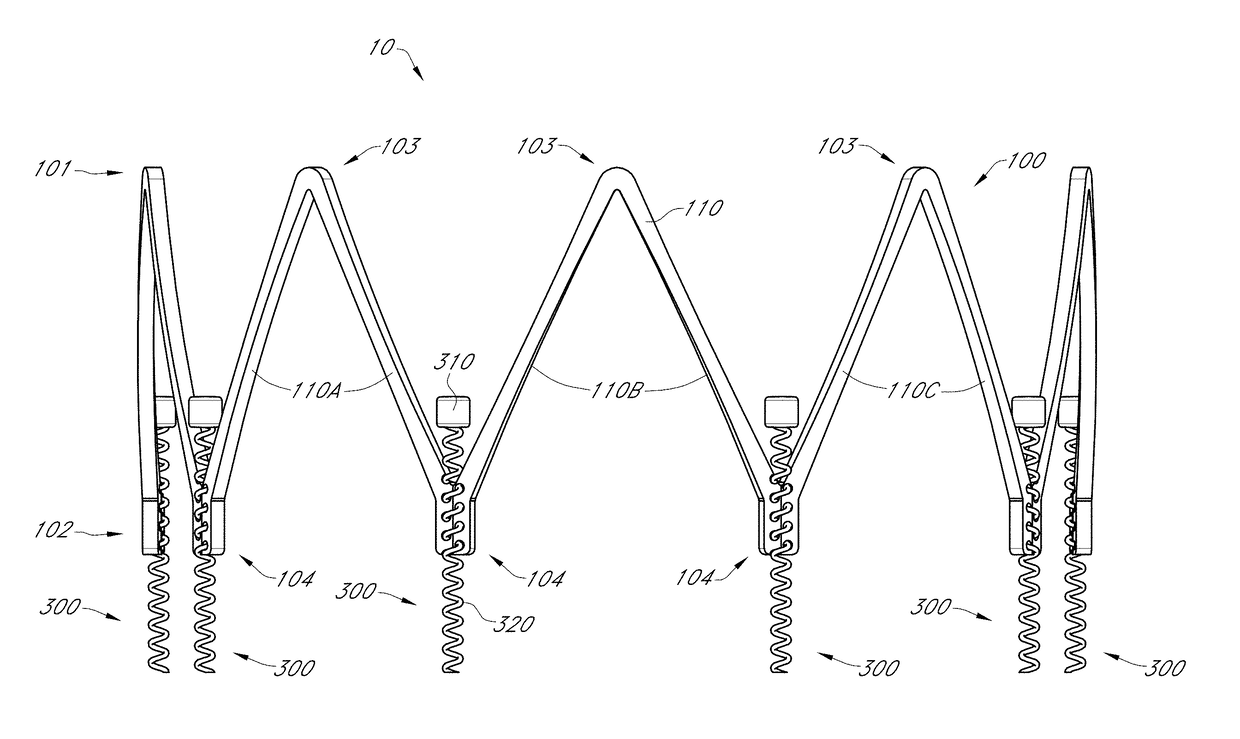
[0011]In one aspect, an implantable heart valve device is disclosed. The device comprises a tubular frame having a proximal end, a distal end and a central lumen extending therethrough, with the frame comprising at least a first pair of adjacent struts joined at a proximally facing apex, and at least a second pair of adjacent struts joined at a distally facing apex. The device further comprises a plurality of distally facing anchors coupled with the frame and configured to embed into tissue surrounding a native mitral valve, a valve coupled with the frame to regulate blood flow through the central lumen, a moveable restraint coupled with the frame and configured to restrain the frame at a desired width and an annular seal carried by the frame, for inhibiting perivalvular leaks.
[0019]In some embodiments, advancing the collar in an axial direction reduces the angle between the first pair of struts thereby reshaping the implant body.

Problems solved by technology

The surgical approach involves risky by-pass surgery, including an opening into the patient's chest and heart chambers to expose the mitral valve for direct viewing and repair.
This technique often slightly reduces the regurgitate flow but does not provide as durable a solution as the surgical ring implantation.

Method used


Image

  • Valve replacement using rotational anchors
  • Valve replacement using rotational anchors
  • Valve replacement using rotational anchors

Examples


Embodiment Construction

[0068]In the following discussion that addresses a number of embodiments and applications, reference is made to the accompanying drawings that form a part hereof, and in which is shown by way of illustration specific embodiments in which the embodiments described herein may be practiced. It is to be understood that other embodiments may be utilized and changes may be made without departing from the scope of the disclosure.

[0069]Various inventive features are described below that can each be used independently of one another or in combination with another feature or features. However, any single inventive feature may not address all of the problems discussed above or only address one of the problems discussed above. Further, one or more of the problems discussed above may not be fully addressed by the features of each embodiment described below.

[0070]Various embodiments of a heart valve device are described. Related delivery and / or deployment systems are also described. The device ma...


PUM


Abstract

Features for a heart valve device are described. The device may include a frame with anchors configured to secure the device to tissue. The frame may include a flared end or skirt for additional securement of the implanted device. The device may include a seal such as a barrier and / or cuff for preventing leakage. The device may contract for endovascular delivery of the device to the heart and expand for securement within the heart, such as the within the native mitral valve annulus. The device may include a replacement valve. The valve may have leaflets configured to re-direct blood flow along a primary flow axis.

Description

INCORPORATION BY REFERENCE TO ANY PRIORITY APPLICATIONS[0001]Any and all applications for which a foreign or domestic priority claim is identified in the Application Data Sheet as filed with the present application are hereby incorporated by reference under 37 CFR 1.57.[0002]This application claims the benefit of priority of U.S. provisional application No. 62 / 116,248, filed Feb. 13, 2015, the entire contents of which are incorporated herein by reference.BACKGROUND[0003]Field[0004]This development relates generally to heart valves, in particular to devices, systems and methods for heart valve replacement.[0005]Description of the Related Art[0006]Mitral valve disease is typically repaired via invasive surgical intervention or by complicated pinching of the leaflets together creating dual, smaller openings or a mitral valve replacement excluding the native valve. The surgical approach involves risky by-pass surgery, including an opening into the patient's chest and heart chambers to e...

Claims


Application Information

Patent Timeline
Patent Type & Authority Patents(United States)
IPC IPC(8): A61F2/24
CPCA61F2/2418A61F2/2409A61F2/2412A61F2230/0069A61F2220/0008A61F2220/0016A61F2/2433A61F2/2463A61F2/2466A61F2230/0091A61F2250/0007A61F2250/001A61F2/2445
Inventor LASHINSKI, RANDALLRUST, MATTHEWMACAULAY, PATRICKGLENN, RICHARD
Owner BOSTON SCI SCIMED INC
Why Eureka
Eureka Blog
Learn More