User interface for a portable power driven system

a technology of user interface and power drive system, which is applied in the direction of portable lifting, hoisting equipment, winding mechanisms, etc., can solve the problems of limiting the length and weight of ropes that can be used, and achieve the effect of increasing the friction between rope and roller

Active Publication Date: 2017-12-26
SKYLOTEC GMBH
View PDF64 Cites 8 Cited by
  • Summary
  • Abstract
  • Description
  • Claims
  • Application Information

AI Technical Summary

Benefits of technology

[0007]The invention is based on the understanding that the operation of the portable power driven system may be simplified in comparison to prior art devices by allowing a combined functionality of the user interface, provided in one single rotatable handle. The handle may accordingly be operated using a single hand of the user, making it possible for the user to at all times keep his hand at the handle and thus making it possible to rapidly change the direction in which the user is advancing the rope. Such a possibility may be specifically useful in relation to a military application where for example the user is approaching a possible enemy. In case of increased danger, the user may directly, without having to move his hand for operating a complex user interface, just switch rotational direction of the handle to rapidly move away form the possible danger and into safety.
[0009]The term rope is here used in its broader sense and is intended to include ropes, wires and cords of whatever nature or size suitable for engaging with the rope grab. The robe grab may in one embodiment comprise a roller (may as be referred to as a rope pulley) formed to at least partly pinch the rope by means of a concave form such as a v- or u-shaped rope engaging face, the rope engaging face formed at the “inside” of the roller for receiving the rope. The inside of the roller may additionally comprise a plurality of ridges for further increasing the friction between the rope and the roller.
[0014]During operation of the portable power driven system, the user is typically securely connected to the above discussed anchoring point, e.g. by means of the sling and carabiner. Accordingly, the handle of the user interface is preferably positioned at the main body of the portable power driven system within an arms length of a user, thus allowing easy operation. Preferably, the handle of the user interface is such positioned that it allows the user to control the handle between the first and the second end position when operated by a single hand of the user.
[0015]Preferably, the portable power driven system further comprises a hinged safety arrangement comprising a safety lid configured to be arranged in a closed state to cover the rope grab during operation of the power driven system, and to be arranged in an opened state for allowing introduction of the rope to the robe grab. Such a safety arrangement minimizes any risks of the user introducing e.g. a hand or similar, efficiently increasing the operational safety of the system.

Problems solved by technology

Further, a winch winds the rope or cable on a spool which limits the length and weight of rope that can be used.

Method used


Image

  • User interface for a portable power driven system
  • User interface for a portable power driven system
  • User interface for a portable power driven system

Examples


Embodiment Construction

[0027]The present invention will now be described more fully hereinafter with reference to the accompanying drawings, in which currently preferred embodiments of the invention are shown. This invention may, however, be embodied in many different forms and should not be construed as limited to the embodiments set forth herein; rather, these embodiments are provided for thoroughness and completeness, and fully convey the scope of the invention to the skilled addressee. Like reference characters refer to like elements throughout.

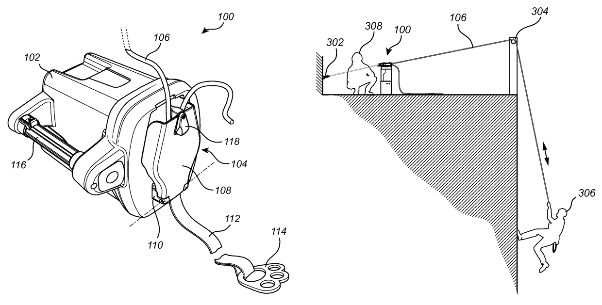
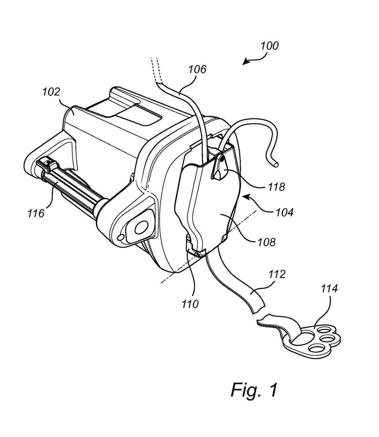
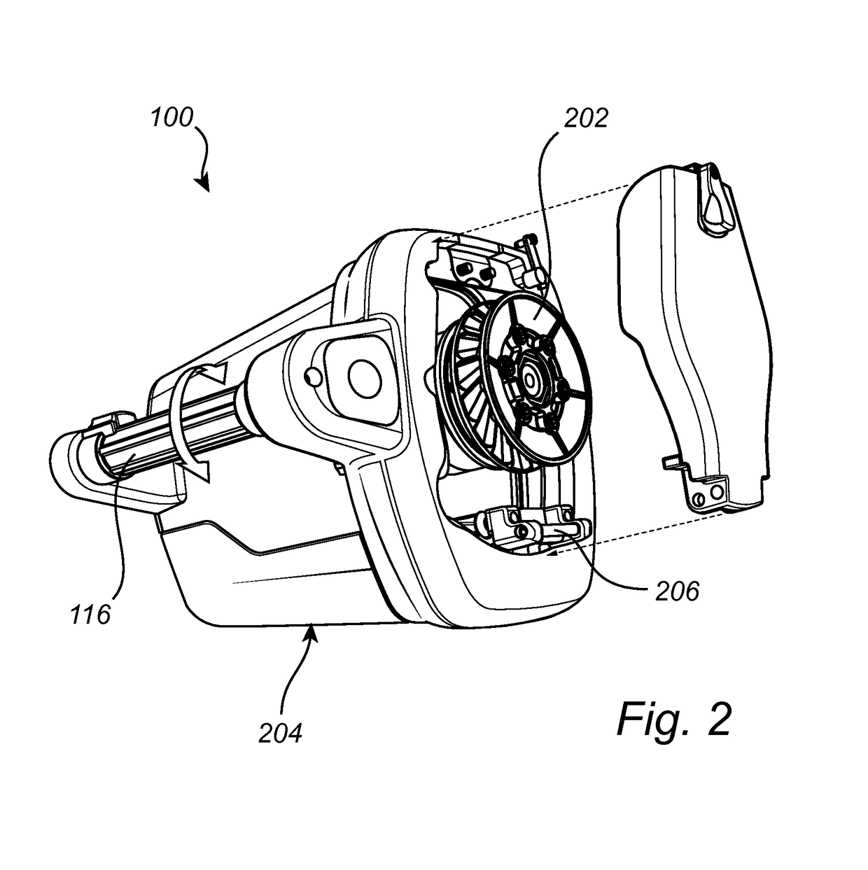
[0028]Referring now to the drawings and to FIGS. 1 and 2 in particular, there is depicted a portable power driven system 100 according to a possible embodiment of the invention. The power driven system 100 comprises a motor and a rope grab 202, the motor and the rope grab 202 being connected to each other by means of for example a drive shaft (possibly also including a gearbox or similar). The motor is an electrical motor further comprising a rechargeable batte...


PUM


Abstract

The present invention relates to a user interface for a portable power driven system, specifically in relation to an integrated user interface for controlling such an arrangement, and being applicable for example in relation to an ascender / descender arrangement. The invention also relates to a corresponding method and computer program product for operating such a portable power driven system.

Description

TECHNICAL FIELD[0001]The present invention relates to a user interface for a portable power driven system, specifically in relation to an integrated user interface for controlling such an system, and being applicable for example in relation to an ascender / descender arrangement. The invention also relates to a corresponding method and computer program product for operating such a portable power driven system.BACKGROUND OF THE INVENTION[0002]Powered personal lifting devices assist personnel in scaling vertical surfaces. Motorized winches are used to raise or lower personnel on platforms or harnesses attached to ropes. A winch must be anchored to a solid platform above the load or use pulleys coupled to the platform to hoist the load. Further, a winch winds the rope or cable on a spool which limits the length and weight of rope that can be used. Hoists, usually with compound pulleys or reducing gears are used to raise or lower individuals or platforms and must be suspended from a secur...

Claims


Application Information

Patent Timeline
Patent Type & Authority Patents(United States)
IPC IPC(8): B66D3/20B66D1/74B66D3/00
CPCB66D3/20B66D3/006B66D1/7415
Inventor MELIN, MICHAELSUNDMAN, PETER
Owner SKYLOTEC GMBH
Why Eureka
Try Eureka