Plug-in coupling for a pipe, in particular for water conduits

a plug-in coupling and water conduit technology, which is applied in the direction of couplings, pipes/joints/fittings, mechanical devices, etc., can solve the problems of significant increase in construction effort, damage to the sealing ring downstream of the locking ring, and difficulty in respect of the available space for the arrangement of the protective ring in the plug-in coupling. , to achieve the effect of minimising the required space, facilitating handling and reducing construction complexity

Active Publication Date: 2018-01-02
KE KELIT KUNSTSTOFFWERK GMBH
View PDF12 Cites 1 Cited by
  • Summary
  • Abstract
  • Description
  • Claims
  • Application Information

AI Technical Summary

Benefits of technology

[0009]A considerable constructional simplification is achieved at first by connecting the protective ring to an annular body that is already present, because no additional constructional part is required. As a result, the otherwise existing problem concerning lack of space is thus also advantageously solved because the combination of the protective ring with the already provided annular body allows minimising the required space. The connection of the protective ring to the annular body by a predetermined breaking connection not only ensures the entrainment of the protective ring when the face end of the pipe end is inserted into the coupling sleeve and severs the protective ring from the annular body once the protective ring enclosing the face end is entrained by the pipe end in the axial direction, but it also simplifies handling because the protective ring does not form any loose component and accordingly the coupling sleeve is assigned to an installation position which is constructionally predetermined. The protective ring enclosing the face end of the pipe end from the outside thus forms a driver limit stop, which after the severing of the protective ring from the annular body ensures that the protective ring enclosing the face end and the subsequent outer edge of the pipe end covers the sealing ring relative to the pipe end when the face end of the pipe end is moved past the sealing ring, so that the pipe end is unable to damage the sealing ring with its face end region. The protective ring is drawn off the sealing ring again by the displacement of the pipe end to an insertion position which is usually limited by a limit stop, which sealing ring can then rest in a sealing fashion under respective pretensioning on the outside jacket of the pipe end.
[0010]For the entrainment of the protective ring and for the protection of the sealing ring it is merely necessary to provide engagement around the face end of the pipe end by the protective ring. The entrainment of the protective ring by the pipe end is improved however if the protective ring has a U-shaped cross-section, which leads to the consequence that the protective ring engages beyond the face end of the pipe end on the outside and inside.

Problems solved by technology

Since it can be expected on construction sites that the pipe ends to be connected are not processed properly during or after cutting to size, there is a likelihood that during the insertion of the pipe end into the coupling sleeve the sealing ring arranged downstream of the locking ring is damaged by the face end of the pipe end.
Apart from the fact that such a protective ring leads to a considerably increased constructional effort in a plug-coupling with a coupling sleeve accommodating the inserted pipe end, there are difficulties in respect of available space for the arrangement of a protective ring in plug-in couplings of this kind.
Apart from the fact that the axial securing of the pipe end by a frictionally engaged press connection with a pipe retainer via a locking ring provided with retaining claws provides constructional conditions that are not comparable, the protective sleeve must be placed on the pipe end, which makes handling more difficult and requires an additional loose constructional part.

Method used


Image

  • Plug-in coupling for a pipe, in particular for water conduits
  • Plug-in coupling for a pipe, in particular for water conduits
  • Plug-in coupling for a pipe, in particular for water conduits

Examples


Embodiment Construction

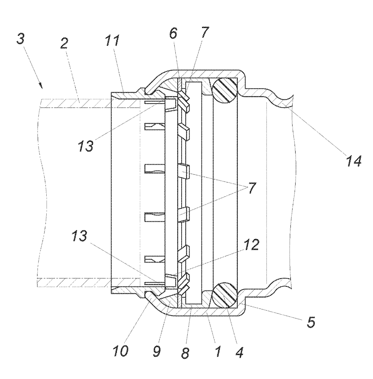
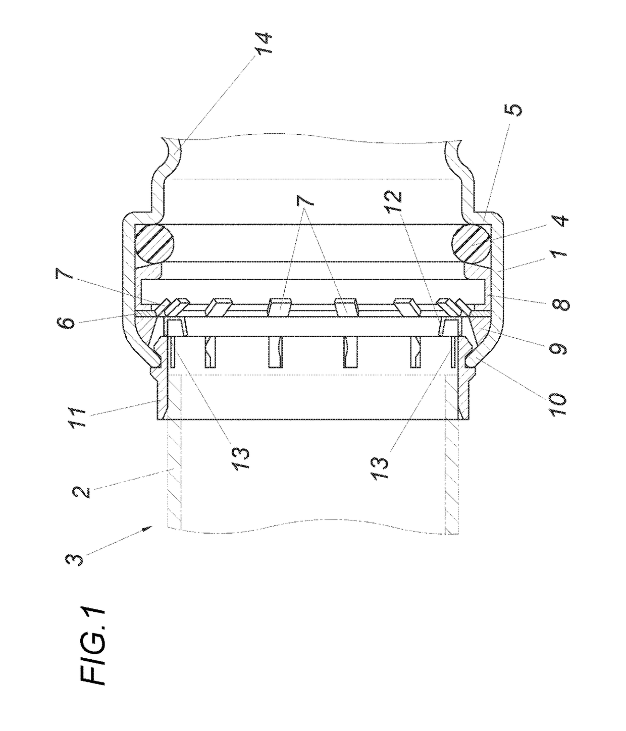
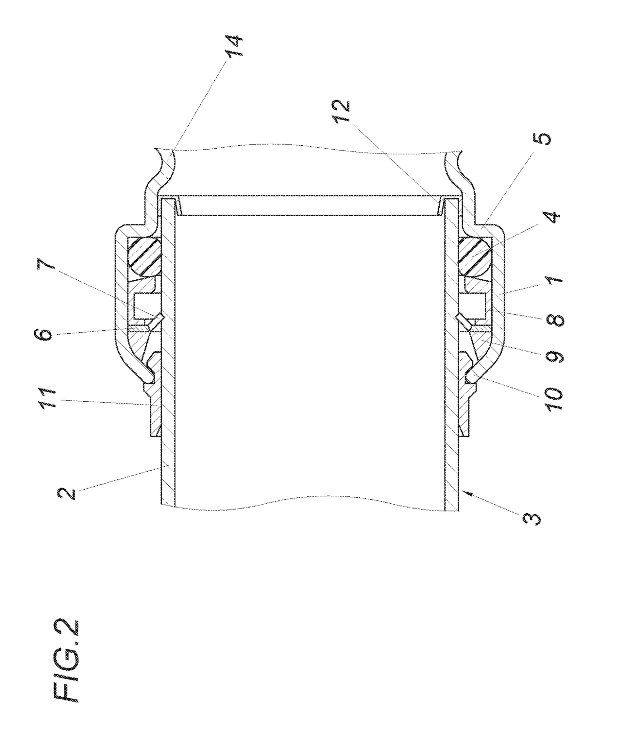
[0017]The plug-in coupling in accordance with the embodiment according to FIGS. 1 and 2 comprises a coupling sleeve 1, into which the pipe end 2 of a pipe to be connected can be inserted. The sealing between the coupling sleeve 1 and the outer jacket of the pipe end 2 occurs by way of a sealing ring 4 which rests on a shoulder 5 of the coupling sleeve 1 in the plug-in direction. The pipe end 2 inserted into the coupling sleeve 1 is axially retained against extraction from the coupling sleeve 1 by means of a locking ring 6 upstream of the sealing ring 4. The locking ring 6 comprises retaining claws 7 for this purpose, which extend in an inclined fashion in the plug-in direction and rest resiliently with their sharp-edged face ends on the outer jacket of the pipe end 2, so that the retaining claws 7 axially retain the pipe end 2 under automatic interlocking when an attempt is made to pull the pipe end 2 from the coupling sleeve 1. The axial support of the locking ring 6 occurs by way ...


PUM


Abstract

A plug-in coupling for a pipe, especially for water conduits, includes a coupling sleeve receiving the pipe end, includes a sealing ring which is inserted into the coupling sleeve, and includes a locking ring which is mounted upstream of the sealing ring in the plug-in direction of the pipe end and forms retaining claws which protrude with respect to the pipe end and are inclined in the plug-in direction. The plug-in coupling also includes an annular body which is similarly mounted upstream of the sealing ring and is supported axially in the plug-in direction in relation to the coupling sleeve. The annular body includes a protective ring for surrounding the face end of the pipe end from the outside, which protective ring is connected via a predetermined breaking connection.

Description

CROSS REFERENCE TO RELATED APPLICATIONS[0001]This application is the National Stage of PCT / AT2013 / 050177 filed on Sep. 9, 2013, which claims priority under 35 U.S.C. §119 of Austrian Application No. A 50371 / 2012 filed on Sep. 10, 2012, the disclosure of which is incorporated by reference. The international application under PCT article 21(2) was not published in English.FIELD OF THE INVENTION[0002]The invention relates to a plug-in coupling for a pipe, especially for water conduits, comprising a coupling sleeve receiving the pipe end, a sealing ring which is inserted into the coupling sleeve, a locking ring which is mounted upstream of the sealing ring in the plug-in direction of the pipe end and forms retaining claws which protrude with respect to the pipe end and are inclined in the plug-in direction, and an annular body which is similarly mounted upstream of the sealing ring and is supported axially in the plug-in direction in relation to the coupling sleeve.DESCRIPTION OF THE PR...

Claims


Application Information

Patent Timeline
Patent Type & Authority Patents(United States)
IPC IPC(8): F16L37/00F16L37/091
CPCF16L37/091F16L2201/80
Inventor RATSCHMANN, ELMARLINZNER, WERNER
Owner KE KELIT KUNSTSTOFFWERK GMBH
Why Eureka
Try Eureka