Method and apparatus for detecting dilute concentrations of radioactive xenon in samples of xenon extracted from the atmosphere

a radioactive xenon and sample technology, applied in the field of methods and apparatus for detecting dilute concentrations of radioactive xenon, can solve the problems of not quite as good detection limits as arsa and sauna, no optical isolation between the two scintillators, and the technology limit has been reached, so as to reduce the cross detector background, reduce interference, and reduce the cross detector cross section

Active Publication Date: 2018-01-02
XIA
View PDF0 Cites 3 Cited by
  • Summary
  • Abstract
  • Description
  • Claims
  • Application Information

AI Technical Summary

Benefits of technology

[0068]The present invention teaches techniques, both method and apparatus, for measuring the concentrations of multiple dilute radioxenon isotopes in a gaseous sample in a manner that lowers minimum detectable levels (MDLs) by both lowering backgrounds from naturally occurring radiation and by also reducing interferences between the radioisotopes themselves. The method allows lower MDLs to be obtained using shorter counting times and smaller volumes of atmosphere from which the radioxenon sample is extracted.
[0074]In beta-gamma radioxenon detectors the major source of background counts arises from environmental radiation, both cosmic and terrestrial, that Compton scatters within the detector producing “coincident” events unrelated to the decay of Xe radioisotopes. In working with our invention detector we have discovered that [electron|photon] Compton scattering events are over a factor of ten times more likely to occur within the same sub-detector than between sub-detectors. Therefore, in preferred embodiments, when a double coincidence between an electron and a photon occurs in the same sub-detector, the two energies are used to record a point in a separate two-dimensional [electron|photon] histogram which has its own ROIs and the counts within these ROIs contribute a separate term toward the estimation of the concentrations of the several radioxenon isotopes. This method results in a substantial background reduction in the two-dimensional histogram used for the remaining [electron|photon] coincidences.
[0075]As a practical matter of fabricating our preferred embodiments, we place an optical coupling element between the second detector element and the photodetector to provide clearance space for the latter in the volume surrounding the fully assembled set of N sub-detectors. In some embodiments the coupling element is made of a material selected so that its index of refraction lies between those of the second detector element and the photodetector to optimize the transmission of light between them. In other embodiments, the coupling can be a third scintillator detector element, whose decay time differs sufficiently from the first and second detector elements' decay times so that the electronics can distinguish between them. A factor of four to five is typically sufficient for reasonable performance. If it is made of a higher density material, this third detector element can be used to increase the sub-detector's detection efficiency for higher energy gamma-rays. It can also be used as an active veto system to electronically shield the sub-detector against cosmic ray events and thereby reduce the background in the detector assembly.
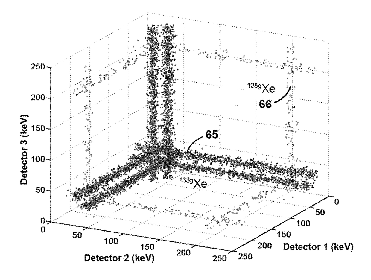
[0078]The design further reduces the background caused by inter-isotope interferences, which were described above, according to a principle we call “geometric partitioning.” As discussed, the major interference is caused by 133gXe, which decays with the triple coincident emission of a β particle, a conversion electron (CE), and a Cs-Kα x-ray, but is detected in prior art (β / γ detectors as a double coincidence between the electron detector (β+CE) and the photon detector (x-ray). Because the β energy is variable, some of these events fall into ROIs set for 131mXe and 133mXe, which both decay with the double coincident emission of a CE and a Xe-Kα x-ray. In the present invention, the N detectors partition the solid angle surrounding the radioxenon cell into N distinct regions. Therefore, when a 133gXe decays and the x-ray, CE and β are all emitted randomly into 4π solid angle, the chance that the CE and β hit the same electron detector is approximately only 1 / N. Thus the great majority of events deposit energy in one photon detector and 2 electron detectors, are recognized as triple coincidences, and removed entirely from the double coincidence decay histograms. This process can be over 90% efficient, thereby reducing the “interference” background by an order of magnitude.
[0079]Backgrounds can be further reduced by using a variant of the phoswich detector that has three scintillating elements instead of two. In the preferred implementation presented above, the phoswich detector comprises a low Z, typically organic, scintillator that is sensitive to electrons backed by a higher Z, typically inorganic scintillator such as NaI or CsI that is sensitive to x-rays and gamma-rays. As is common practice with phoswich detectors, the decay constants of the two scintillators are different so that one can use pulse shape analysis to distinguish whether one, the other, or both are emitting light in any given event. These scintillators are coupled to an optical sensor, typically a photomultiplier, using a transparent connecting member that acts as a light guide. In the three element variant the light guide is replaced by a third scintillator, whose decay constant is different from the first two and detected light from this scintillator is used as a veto against minimum ionizing cosmogenic muons, as is well known to those skilled in the art. Because a large fraction of background events are cosmogenic in origin, this serves to further reduce both the double and triple coincidence backgrounds. With appropriate analysis, these third scintillators can also provide enhanced sensitivity to the higher energy γ's emitted by 135Xe at 250 keV.
[0080]We disclose two preferred embodiments. In the first, six phoswich detectors have their square faced detectors placed on the surface of a cube to form the radioxenon cell. In the second, twelve phoswich detectors have their pentagonal faced detectors placed on the surface of a dodecahedron to form the radioxenon cell. The first design requires fewer components and sets of processing electronics. However its crystals are larger, it has higher backgrounds and rates of interference. The second design achieves lower backgrounds and twice as good interference rejection, but at the obvious cost of twice as many detectors and sets of electronics.

Problems solved by technology

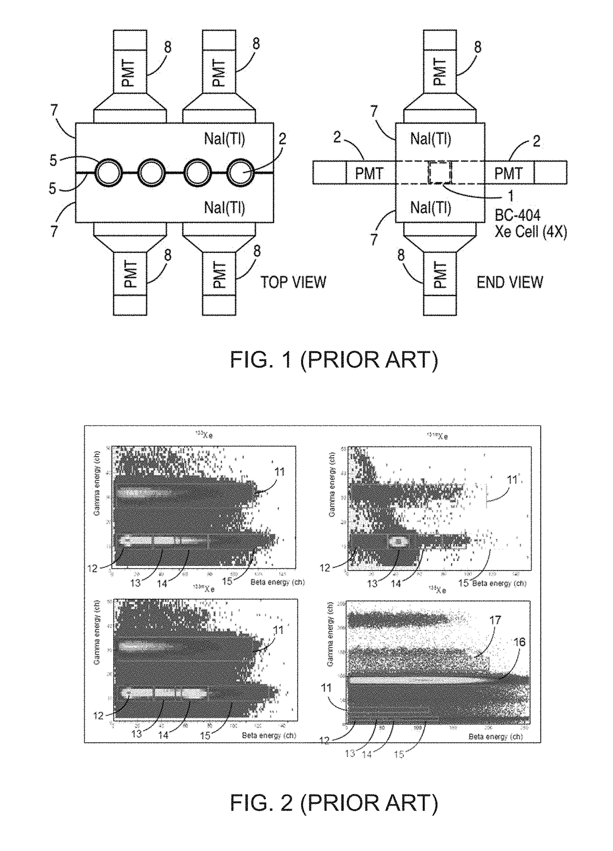
Detection limits are not quite as good as ARSA and SAUNA, primarily due to the less efficient light collection from the BC404 xenon cell 26.
Further, there is no optical isolation between the two scintillators—the single PMT sees both the electron detector and the photon detector.
However, this proposal assumed that, for technical reasons discussed below, technology limits have been reached and lower MDC's cannot be achieved with current sample volumes and / or shorter counting times.
Because these are spike sources, one cannot see the Compton scattering background that would normally provide a major limitation on achievable MDC's.
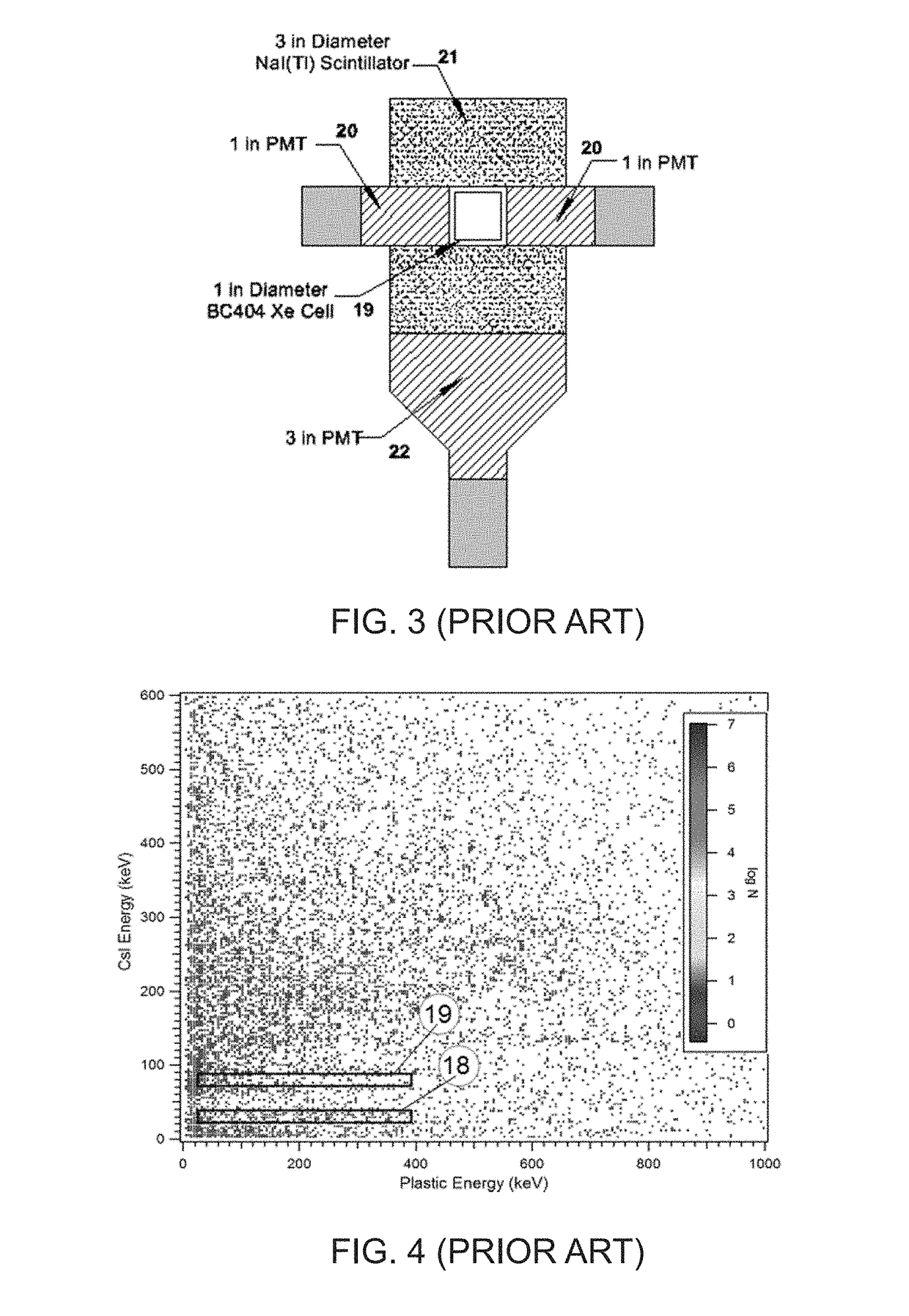
However, this also resulted in very low photon detection efficiencies, with almost no cross section for photons above 30 keV.
The complexity of 24 detectors and their associated electronics, plus the need for cooling to achieve the reported energy resolution suggest that it would be very difficult to commercialize this design.

Method used


Image

  • Method and apparatus for detecting dilute concentrations of radioactive xenon in samples of xenon extracted from the atmosphere
  • Method and apparatus for detecting dilute concentrations of radioactive xenon in samples of xenon extracted from the atmosphere
  • Method and apparatus for detecting dilute concentrations of radioactive xenon in samples of xenon extracted from the atmosphere

Examples


Embodiment Construction

[0013]1. The principle of geometrical partitioning[0014]2. Background measurements[0015]2.1 Detector configuration[0016]2.2 Double coincidence backgrounds[0017]2.3 Triple coincidence backgrounds[0018]3. Estimated detection limits[0019]4. Reduction of interferences[0020]5. Preferred embodiment with N equal to[0021]6. Preferred embodiment with N equal to[0022]7. Using a scintillator as the optical coupler[0023]8. Operation as a complete detector system[0024]9. Additional detector system embodiments[0025]10. References[0026]11. Conclusion

Abstract of the Disclosure

BACKGROUND OF THE INVENTION

Field of the Invention

[0027]The present invention relates generally to systems for detecting very low levels of radioactive xenon isotopes (also “xenon radioisotopes,” or simply “radioxenon”) in samples of xenon extracted from the atmosphere and, in particular, to detectors for this purpose of the type commonly referred to by those skilled in the art as “beta / gamma” detectors.

A Synopsis of Current Pr...


PUM


Abstract

A method and apparatus for measuring the concentrations of radioxenon isotopes in a gaseous sample wherein the sample cell is surrounded by N sub-detectors that are sensitive to both electrons and to photons from radioxenon decays. Signal processing electronics are provided that can detect events within the sub-detectors, measure their energies, determine whether they arise from electrons or photons, and detect coincidences between events within the same or different sub-detectors. The energies of detected two or three event coincidences are recorded as points in associated two or three-dimensional histograms. Counts within regions of interest in the histograms are then used to compute estimates of the radioxenon isotope concentrations. The method achieves lower backgrounds and lower minimum detectable concentrations by using smaller detector crystals, eliminating interference between double and triple coincidence decay branches, and segregating double coincidences within the same sub-detector from those occurring between different sub-detectors.

Description

CROSS-REFERENCE TO RELATED APPLICATION[0001]This application claims the benefit of U.S. Patent Application No. 62 / 145,393, filed Apr. 9, 2015, for “Method and Apparatus for Detecting Dilute Concentrations of Radioactive Xenon in Samples of Xenon Extracted From the Atmosphere” (inventors William K. Warburton and Wolfgang G. Hennig), the entire disclosure of which is hereby incorporated by reference for all purposes.STATEMENT AS TO RIGHTS TO INVENTIONS MADE UNDER FEDERALLY SPONSORED RESEARCH OR DEVELOPMENT[0002]The U.S. Government has rights in this invention pursuant to Contract No. DE-SC0011301 awarded by the Department of Energy.TABLE OF CONTENTSStatement as to Rights to Inventions Made Under Federally Sponsored Research or DevelopmentCross-Reference to Related ApplicationBACKGROUND OF THE INVENTION[0003]Field of the Invention[0004]A Synopsis of Current Prior Art[0005]The ARSA detector[0006]The SAUNA detector[0007]The PNNL improved detector[0008]The PhosWatch detector[0009]Issues f...

Claims


Application Information

Patent Timeline
Patent Type & Authority Patents(United States)
IPC IPC(8): G01T1/17G01T1/208G01T1/20G01T1/178
CPCG01T1/178G01T1/2018G01T1/208
Inventor WARBURTON, WILLIAM K.HENNIG, WOLFGANG G.
Owner XIA
Why Eureka
Try Eureka