Optical imaging lens
- Summary
- Abstract
- Description
- Claims
- Application Information
AI Technical Summary
Benefits of technology
Problems solved by technology
Method used
Image


Examples
first embodiment
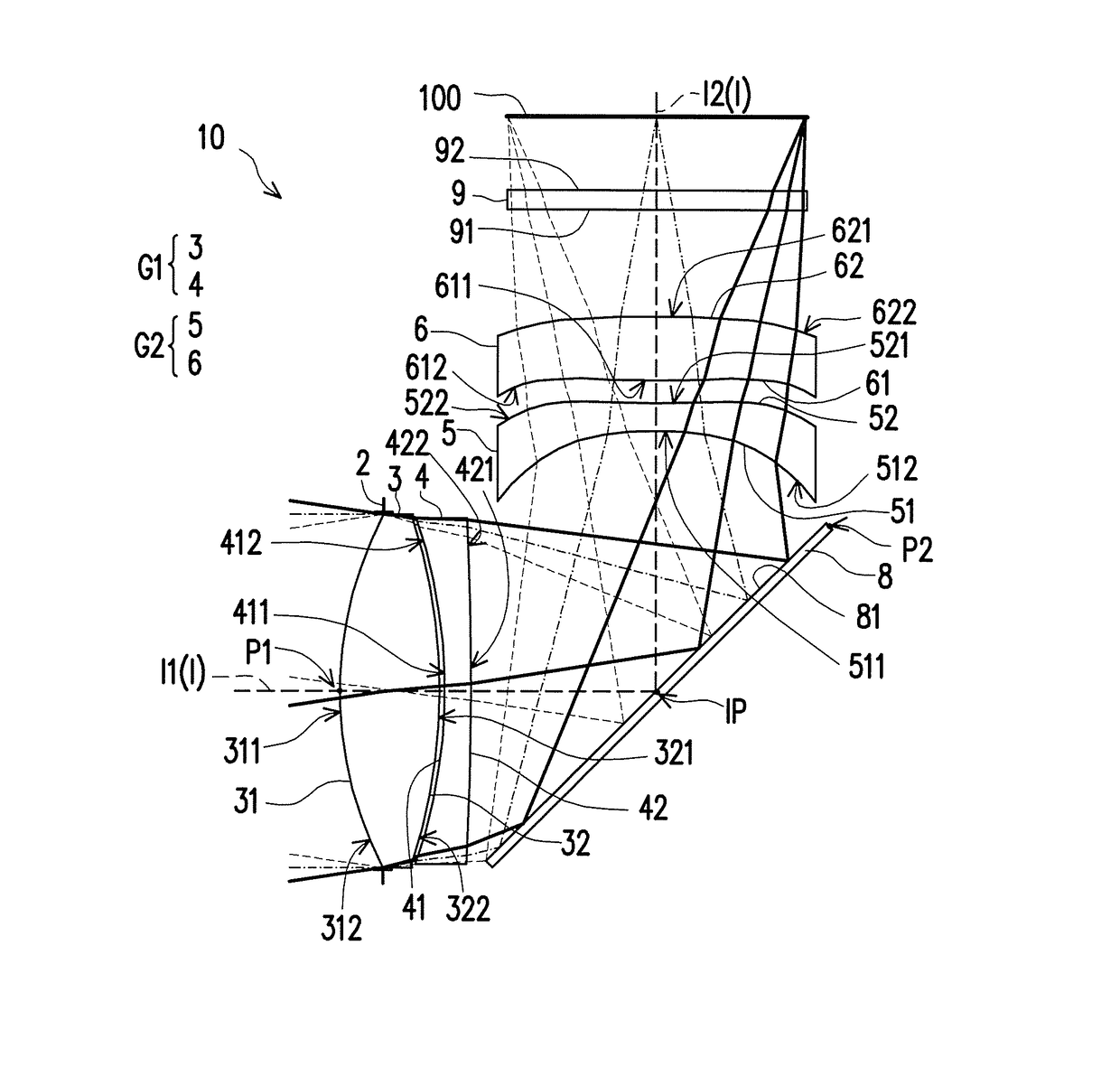
[0081]In addition, the relations among important parameters pertaining to the optical imaging lens 10 in the first embodiment are shown in FIG. 42.
[0082]wherein,
[0083]T1 represents a thickness of the first lens element 3 along the first optical axis I1;
[0084]T2 represents a thickness of the second lens element 4 along the first optical axis I1;
[0085]T3 represents a thickness of the third lens element 5 along the second optical axis I2;
[0086]T4 represents a thickness of the fourth lens element 6 along the second optical axis I2;
[0087]TF represents a thickness of the filter 9 along the second optical axis I2;
[0088]G12 represents an air gap between the first lens element 3 and the second lens element 4 along the first optical axis I1;
[0089]G2M represents an air gap between the second lens element 4 and the intersection point IP along the first optical axis I1;
[0090]GM3 represents an air gap between the intersection point IP and the third lens element 5 along the second optical axis I2;...
second embodiment
[0123]The detailed optical data pertaining to the optical imaging lens 10 is shown in FIG. 12, and the effective focal length of the total system in the second embodiment is 11.252 mm, the HFOV thereof is 13.060°, Fno thereof is 2.970, and the TTL thereof is 11.147 mm.
[0124]FIG. 13 shows the aspheric coefficients used in the formula (1) of the object-side surface 31 of the first lens element 3 through the image-side surface 62 of the fourth lens element 6 in the second embodiment.
[0125]In addition, the relations among important parameters pertaining to the optical imaging lens 10 in the second embodiment are shown in FIG. 42.
[0126]The longitudinal spherical aberration of the second embodiment shown in FIG. 11A is simulated in the condition that the pupil radius is 1.9000 mm. According to the longitudinal spherical aberration diagram of the second embodiment shown in FIG. 11A, a deviation of the imaging points of the off-axis rays of different heights is controlled within a range of ...
third embodiment
[0129]The detailed optical data pertaining to the optical imaging lens 10 is shown in FIG. 16, and the effective focal length of the total system in the third embodiment is 10.237 mm, the HFOV thereof is 14.099°, Fno thereof is 2.710, and the TTL thereof is 10.231 mm.
[0130]FIG. 17 shows the aspheric coefficients used in the formula (1) of the object-side surface 31 of the first lens element 3 through the image-side surface 62 of the fourth lens element 6 in the third embodiment.
[0131]In addition, the relations among important parameters pertaining to the optical imaging lens 10 in the third embodiment are shown in FIG. 42.
[0132]The longitudinal spherical aberration of the third embodiment shown in FIG. 15A is simulated in the condition that the pupil radius is 1.9000 mm. According to the longitudinal spherical aberration diagram of the third embodiment shown in FIG. 15A, a deviation of the imaging points of the off-axis rays of different heights is controlled within a range of ±0.04...
PUM
 Abstract
Description
Claims
Application Information
 - R&D Engineer
- R&D Manager
- IP Professional
- Industry Leading Data Capabilities
- Powerful AI technology
- Patent DNA Extraction
Browse by: Latest US Patents, China's latest patents, Technical Efficacy Thesaurus, Application Domain, Technology Topic.
© 2024 PatSnap. All rights reserved.Legal|Privacy policy|Modern Slavery Act Transparency Statement|Sitemap