
Method and apparatus for combination of localization microscopy and structured illumination microscopy

a technology of localization microscopy and structured illumination, applied in the field of fluorescent microscopes, can solve the problems of limited ability, long acquisition time, and small and achieve the effect of reducing the size of the illuminated region of the sampl

Active Publication Date: 2018-01-23
FORSCHUNGSZENT MIKROSKOPIE FZM LUCIAOPTICS GEMEINNUTZIGE UG
View PDF12 Cites 5 Cited by
  • Summary
  • Abstract
  • Description
  • Claims
  • Application Information

AI Technical Summary

Benefits of technology

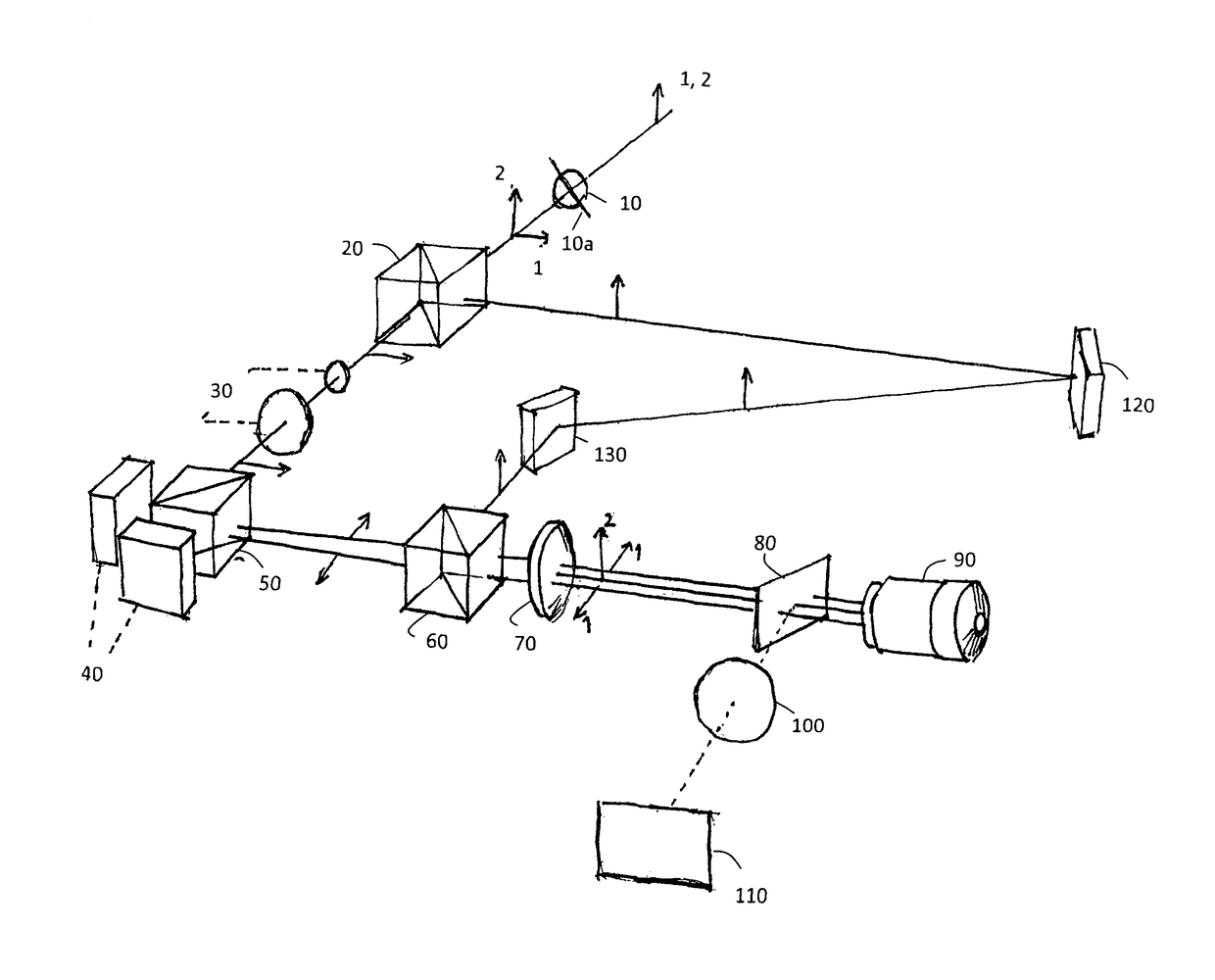
[0018]Advantageously, it is possible to carry out individual structural illumination microscopy (SIM / SMI) and localization microscopy (LM) measurements as well as modified localization microscopy measurements, which utilize structured illumination light with the same optical set-up. Accordingly, a fluorescence microscope with a less costly, less critical and more stable optical setup as compared to prior art solutions may be realized.
[0019]Further, the combination of the two different microscopic techniques, localization microscopy and structured illumination microscopy, in a single optical set-up allows to easily obtain images of the same region of interest in the object (sample) plane (x,y) and in the same (coinciding) z-planes by both methods. This is very difficult if not impossible to realize with two different optical set-ups: one for localization microscopy and one for structured illumination microscopy. The possibility to obtain images of the same region of the sample in the same coinciding z-plane may considerably improve the precision of the measurements and the ability to visualize and / or obtain structural information of complex, three-dimensional samples. Accordingly, high resolution three-dimensional images of the sample or respectively high resolution three-dimensional structural data with improved accuracy may be obtained.
[0024]The combination of the two methods (localization microscopy and structured illumination microscopy) is particularly suitable for obtaining images of autofluorescent structures in a sample in combination with conventional labelling methods. In particular, the structured illumination microscopy may be utilized for visualizing structures in a sample by detecting the (often broad band) autofluorescent light emitted by autofluoresent fluorophores within different structures of the sample, such as for example retina proteins, lipofuszin-granula, etc. Generally, such images cannot be obtained by means of localization microscopy due to the lacking switching capabilities of the autofluorescent fluorophores. In addition, by carrying out localization microscopy measurements, it is possible to visualize additional, previously labelled structures or compartments. To this extent the illumination may be switched to localization illumination mode, in which the light propagates through the localization illumination light. Since the autofluorescent fluorophores generally exhibit little bleaching even at high illumination intensities and cannot be switched between a bright and a dark state, it is possible to separate the image data obtained by structured illumination microscopy from the image data obtained by localization microscopy. A subsequent overlay of the structured illumination microscopy data enables simultaneous visualization of both autofluorescent structures and fluorescently labelled structures within the observed sample. If by means of suitable mathematical methods the localisation image data are converted into corresponding structural data, it is possible to combine in one image both autofluorescent structure data / information and structure data / information obtained from the localization image data.

Problems solved by technology

The diffraction limits this ability and thus the resolution.
An illumination light with low intensity results in a very long acquisition time.
This problem is typical for many imaging fluorescent techniques.
In addition, the size of illuminated region of the sample is usually very small.
However, this reduces the amount of information acquired at each measurement.
For the above reasons a combination of structured illumination microscopy and localization microscopy was considered very difficult, since either the intensity of the illumination light is too low for localization microscopy measurements or the size of the illuminated region of the sample is too small for structured illumination measurements.

Method used


Image

  • Method and apparatus for combination of localization microscopy and structured illumination microscopy
  • Method and apparatus for combination of localization microscopy and structured illumination microscopy
  • Method and apparatus for combination of localization microscopy and structured illumination microscopy

Examples


Embodiment Construction

[0042]The term “fluorescence” within the scope of the present application, is to be understood as any photon-interaction wherein there are differences between the illumination, respectively excitation spectrum, and the emission spectrum of the same object which cannot be explained based on the monochromatic absorption only. That includes for example in particular multiphoton interactions, by which the excitation wavelengths can be greater than the emission wavelengths. Thus the term fluorescence will be also used in the sense of this application for the closely related phenomena as “luminescence” and “photophosphorescence” or short “phosphorescence”. This includes in particular the cases of longer fluorescence duration, for example in the millisecond range. The use of phosphorescent optical labels, respectively the use of phosphorescent molecules for optical labeling instead of fluorescent molecules may be for example advantageous in view of improving the in vivo applicability of th...


PUM

PropertyMeasurementUnit
angleaaaaaaaaaa
anglesaaaaaaaaaa
anglesaaaaaaaaaa

Abstract

A fluorescence microscope for obtaining super-resolution images of a sample labeled with at least one fluorescent label by combining localization microscopy and structured illumination microscopy is provided. The fluorescence microscope includes one or more light sources, an illumination system having a structured illumination path for illuminating the sample with structured illumination light and a localization illumination path for illuminating the sample with localization illumination light.

Description

CROSS REFERENCE TO RELATED APPLICATIONS[0001]This application is a National Stage Entry of PCT / EP2014 / 001228 filed May 7, 2014, which claims priority from European Patent Application No. EP 13002490.4 filed May 10, 2013, both of which are incorporated herein in their entirety.BACKGROUND[0002]The present invention relates to a fluorescent microscope and a respective method for obtaining super-resolution images of a sample labelled with at least one type fluorescent label by combining localization microscopy and structured illumination microscopy.[0003]The ability of a microscope to distinguishably image small, “point-like” objects is characterized, besides by the contrast, by the resolving power or resolution of the microscope. Due to the diffraction, point objects are seen as blurred disks (called Airy disks) surrounded by diffraction rings. The resolution of a microscope can be defined as the ability to distinguish between two closely spaced Airy disks. In other words, the resoluti...

Claims


Application Information

Patent Timeline
Patent Type & Authority Patents(United States)
IPC IPC(8): G02B21/36G01N21/64G02B21/16G02B27/58G02B21/00
CPCG02B21/367G01N21/6458G02B21/0076G02B21/361G02B27/58G02B21/16G01N2201/0675G01N21/6445
Inventor BEST, GERRITCREMER, CHRISTOPHROSSBERGER, SABRINADITHMAR, STEFAN
Owner FORSCHUNGSZENT MIKROSKOPIE FZM LUCIAOPTICS GEMEINNUTZIGE UG
Learn More