Condenser microphone unit and condenser microphone

a condenser microphone and microphone technology, applied in the field of condenser microphone units, can solve the problems of difficult to ensure the signal-noise ratio (s/n ratio) required for picking up the sound of instruments, and the frequency dependence of sound waves

Inactive Publication Date: 2018-01-23
AUDIO-TECHNICA
View PDF9 Cites 17 Cited by
  • Summary
  • Abstract
  • Description
  • Claims
  • Application Information

AI Technical Summary

Benefits of technology

[0016]Preferably, the diaphragm entirely has first convex-concave patterns each having a rough convex-concave profile with a long period, and second convex-concave patterns each present within the first convex-concave pattern and having a fine convex-concave profile with a short period. Convex portions of the first convex-concave patterns of this diaphragm can be used as the convex ribs.
[0019]According to the present invention, a hollow cylindrical diaphragm electrode, serving as a diaphragm, is disposed along the outer periphery of a fixed electrode pole, serving as a fixed electrode, with convex ribs, serving as spacers, so that sealed spaces are formed for the respective diaphragm regions between the fixed electrode pole and the hollow cylindrical diaphragm electrode and each diaphragm region vibrates in response to the incoming sound waves. Each diaphragm region has a small area and a resonance frequency in a high-frequency range, resulting in a non-directional condenser microphone unit that gives no diffraction effects occurring with sound waves beyond the audio frequency range and that exhibits a high signal-noise ratio.

Problems solved by technology

A hollow cylindrical condenser microphone having a diaphragm at one end generally suffers from diffraction effects resulting from its shape and thus cannot achieve such a performance unless the diameter of the hollow cylinder is made small.
Such a small diameter offers a small effective capacitance between a diaphragm and a fixed electrode, which makes it difficult to ensure a signal-noise ratio (S / N ratio) required for picking up instrument sounds.
This results in frequency-dependence occurring with sound waves beyond the audio frequency range.

Method used


Image

  • Condenser microphone unit and condenser microphone
  • Condenser microphone unit and condenser microphone
  • Condenser microphone unit and condenser microphone

Examples


Embodiment Construction

[0030]Embodiments of the present invention will now be described with reference to FIGS. 1 to 5, although the present invention is not limited to the embodiments.

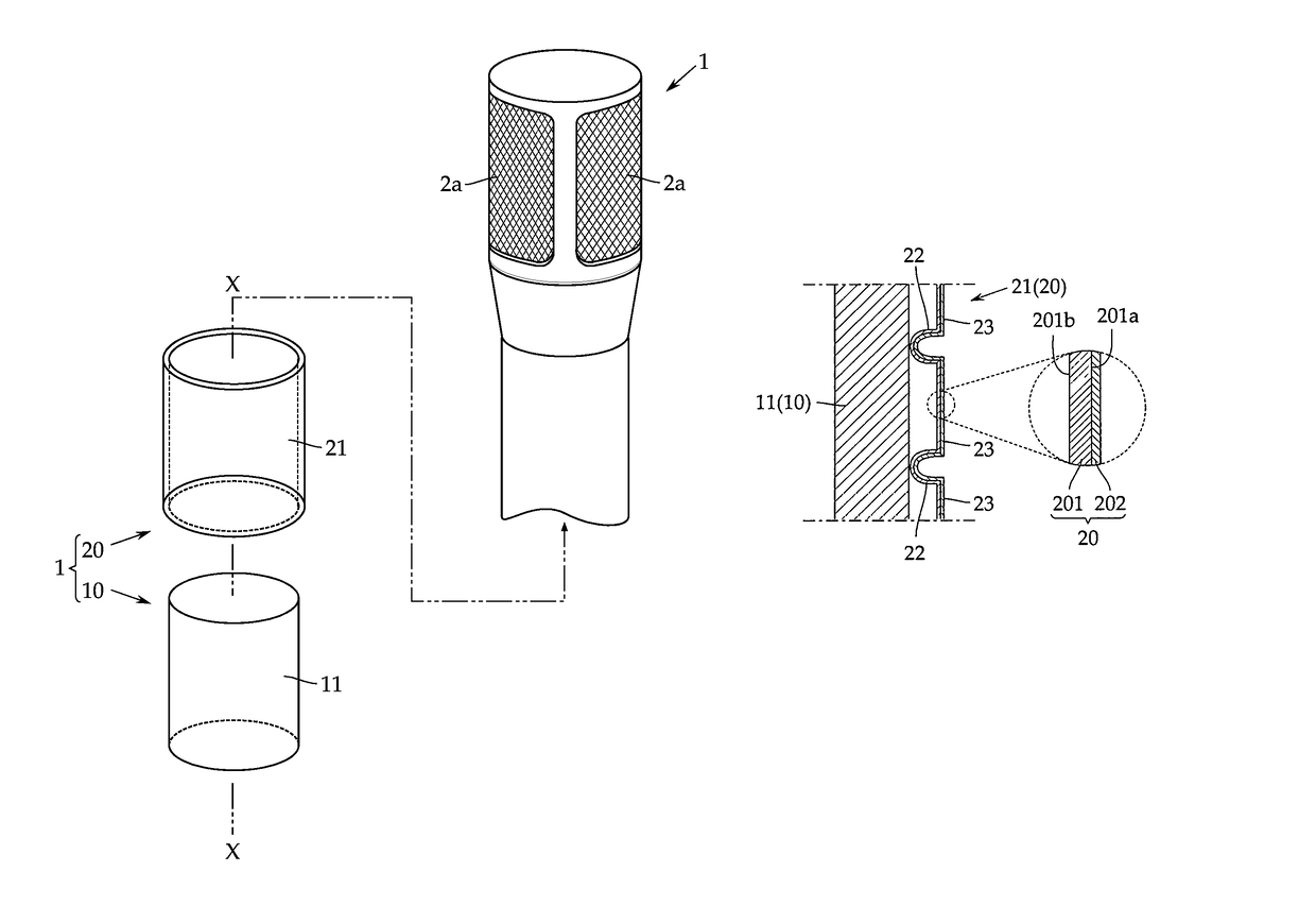
[0031]As shown in FIG. 1, a condenser microphone according to this embodiment basically includes a condenser microphone unit 1 and a microphone case 2 containing the condenser microphone unit 1.

[0032]Referring to “diffraction effects from sound waves produced by a hollow cylinder” shown in FIG. 6 that has been introduced as one of the background arts, in the case where the cylindrical body receives sound waves from 90° to the axis of the hollow cylinder, positioning a diaphragm at this direction eliminates the frequency-dependence occurring with sound waves beyond the audio frequency range regardless of an increase in signal-noise ratio achieved by an increase in the effective area of the capacitor element. The present invention has been made under these findings.

[0033]The condenser microphone unit 1 includes a fixed electr...


PUM


Abstract

A condenser microphone unit that has a capacitor element with a large effective area and a high signal-noise ratio but does not have frequency-dependence occurring with sound waves beyond the audio frequency range. A solid cylindrical fixed electrode pole is used as a fixed electrode. A diaphragm includes a rectangular synthetic resin film having a length smaller than or equal to the axis length of the fixed electrode pole, and a width equal to a circumferential length of the fixed electrode pole, the synthetic resin film including an electrode film on one face and ribs on the other face and entirely partitioned by the ribs into a plurality of diaphragm regions. The synthetic resin film is attached to an entire outer periphery of the fixed electrode pole such that the ribs are in contact with the outer periphery.

Description

RELATED APPLICATIONS[0001]The present application is based on, and claims priority from, Japanese Application No. JP2015-244817 filed Dec. 16, 2015, the disclosure of which is hereby incorporated by reference herein in its entirety.TECHNICAL FIELD[0002]The present invention relates to a non-directional condenser microphone unit that is a high-resolution device capable of picking up sound waves beyond the audio frequency range.BACKGROUND ART[0003]There has recently been an increasing demand for an improvement in sound quality by picking up sound waves beyond the audio frequency range. According to “Hairezoryushon ohdio (saundo) no torikumi (efforts for high-resolution audio (sound))” released by the Japan Audio Society, a general incorporated association, on Jun. 12, 2014, a high-resolution device is defined as a device that has a recording microphone capable of performance in the high-frequency range of 40 kHz or more.[0004]A hollow cylindrical condenser microphone having a diaphrag...

Claims


Application Information

Patent Timeline
Patent Type & Authority Patents(United States)
IPC IPC(8): H04R25/00H04R19/04H04R7/12
CPCH04R19/04H04R7/122H04R2307/025H04R1/222H04R7/14H04R2410/03
Inventor AKINO, HIROSHI
Owner AUDIO-TECHNICA
Why Eureka
Try Eureka