Eureka AIR delivers breakthrough ideas for toughest innovation challenges, trusted by R&D personnel around the world.

Punching apparatus for wire-binding book

Active Publication Date: 2018-01-30
SHIN HEUNG MACHINERY CO
View PDF27 Cites 0 Cited by
  • Summary
  • Abstract
  • Description
  • Claims
  • Application Information

AI Technical Summary

Benefits of technology

The present invention aims to prevent damage to punch pins and extend the life span of a punch device by dividing objects into sheet units and sequentially moving them to a punching device for binding. The operation efficiency is improved, and management and maintenance are easy as the object for binding is returned to the previous process after punching hole operation. Additionally, the size of the object for binding is variously changed, and the clip position of a unit transferring unit is easily moved for stable separating position. The embossed grooves of a guide plate and a table are interlocked, preventing fall while placing the object for binding on the table and improving the operation efficiency.

Problems solved by technology

The apparatuses described above need the process matching the punched coupling holes for wire binding when a sheet or a bunch of sheets is combined into a unit object for binding after coupling holes for binding are punched in the sheet or the bunch of sheets, and therefore the process is very inconvenient.
Further, the binding device of Korean Patent No. 10-0587221 (registered on Jun. 8, 2006) is an apparatus forming two lines so as to have three punching pins or two punching pins within one inch, and this device can bind with a spring after punch regardless of the size of paper, the gap between the punched holes and so on, but since this device has a structure that cannot punch the unit object for binding at once, after performing punching operations several times the additional procedure for combining and matching the punched coupling holes is also needed for spring binding and therefore it is inconvenient.

Method used


Image

  • Punching apparatus for wire-binding book
  • Punching apparatus for wire-binding book
  • Punching apparatus for wire-binding book

Examples


Embodiment Construction

Technical Problem

[0008]Therefore, the embodiments of the present application may solve the problems of prior art described above, and the purpose of the embodiments of the present invention may be for providing a punching apparatus for a wire-binding book which is capable of stably supplying an object for binding to a next wire binding position after easily dividing the object for binding such as a note, a book, an album and so on having various thicknesses into a plurality of sheet units, holding and sequentially moving them and finishing punching operations.

Technical Solution

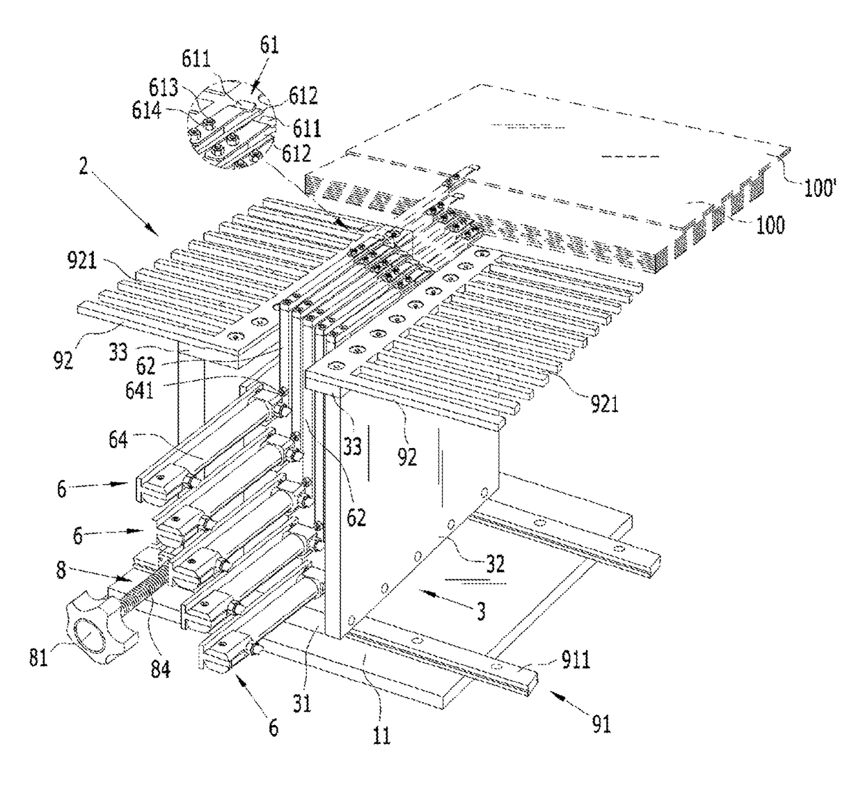
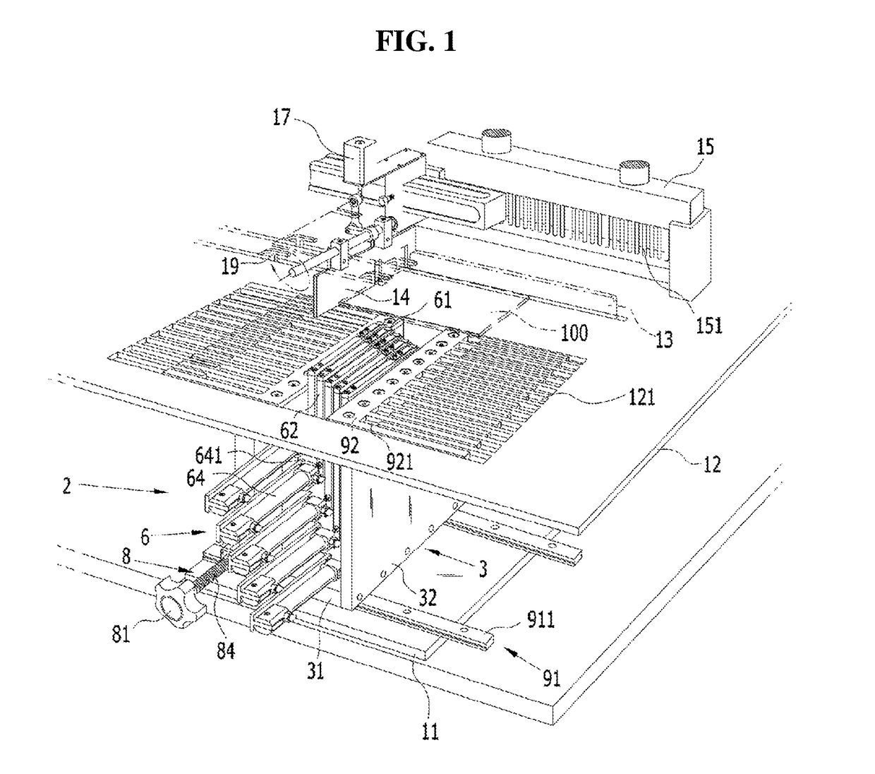
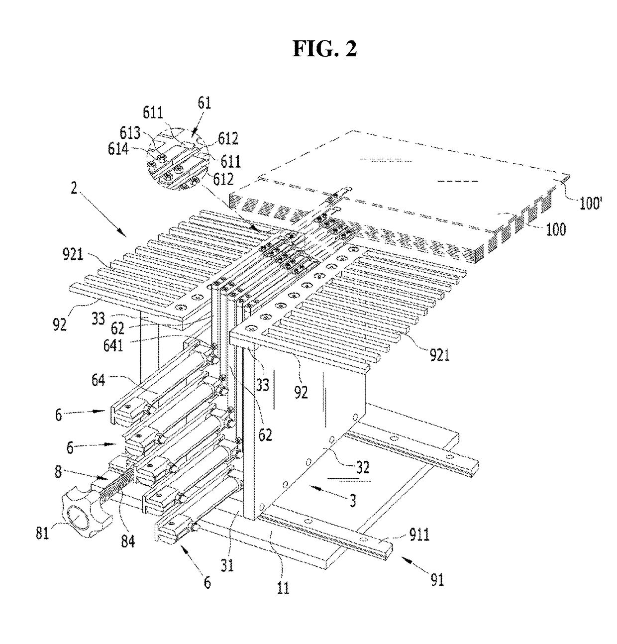
[0009]To achieve the purpose, a punching apparatus for a wire-binding book according to an embodiment of the present invention may comprise a table arranged at an upper portion of a supporting plate, wherein an object for wire binding can be placed on the table, first and second alignment plates arranged at a center portion of the table and configured to be rotatable or movable upward and / or downward, a punchi...


PUM


Abstract

Disclosed is a punching apparatus, for a coil bound notebook, which divides into many an object to be bound such as a notebook, a book, an album and the like, then punches same while sequentially moving same and enables easy feeding of the object to be bound, for which the punching has been completed, to a subsequent coil binding position. A punching apparatus for a coil bound notebook, according to the present invention, has first and second alignment plates which are provided on a table on which an object to be coil bound is placed, a punch for punching into the object to be bound binding holes into which a coil spring is inserted, and a moving means for the object to be bound for moving the object to be bound to and from the punch. The moving means for the object to be bound comprises: a main body having a lower plate which is mounted on a support, a vertical plate which is fixed on the lower plate, and an upper plate which is fixed on the vertical plate so as to have the central part open; an LM guide having a rail which is fixed on the main body and a block which is coupled to the rail; a saddle which is fixed on the block of the LM guide and has a plurality of step layers formed on one side; a plurality of unit moving units which have formed thereon clips, dividing the object to be bound and holding single sheet bundles, to become sequentially higher and each of which is mounted on each of the step layers of the saddle; and a saddle moving unit which has a supporting plate fixed on the saddle, a first cylinder of which an operating shaft is fixed on the supporting plate, a fixing plate for fixing the rear of the first cylinder, and a screw rod for screw coupling one side of the fixing plate, coupling a handle to the front end and rotatably mounted on frontal and rear supporting plates fixed on the main body.

Description

CROSS-REFERENCE TO RELATED APPLICATIONS[0001]This application is the U.S. National Stage of International Patent Application No. PCT / KR2015 / 006895 filed on Jul. 3, 2015, which claims the priority to Korean Patent Application No. 10-2014-0086110 filed on Jul. 9, 2014, the disclosures of which are hereby incorporated in their entireties by reference.TECHNICAL FIELD[0002]Embodiments of the present invention may relate generally to a punching device punching coupling holes for spring binding in an object for binding, more particularly, a punching apparatus for a wire-binding book dividing the object for binding of a note, a book, an album and so on into a plurality and sequentially moving and punching them, and easily supplying the object for binding to a next wire-binding location after punching operation is completed.BACKGROUND[0003]Generally, as shown in FIGS. 7 (A) and (B), objects for binding (1), such as a note, a book, an album and so on, may have production thicknesses different...

Claims


Application Information

Patent Timeline
IPC IPC(8): B26D7/01B42B5/12B26F1/24B65H5/16
CPCB26D7/015B65H5/16B42B5/12B26F1/24B26D7/025B26D7/0608B26F1/14B26D7/01B26F1/02B26F1/32B42F13/00B42F13/404
Inventor LEE, SIN-YOUNG
Owner SHIN HEUNG MACHINERY CO
Why Eureka
Eureka Blog
Learn More