Vehicle lighting device using a multiple-source optical lens

a technology of multiple-source optical lenses and vehicle lighting, which is applied in the direction of refractors, lighting and heating apparatuses, transportation and packaging, etc., can solve the problems of generating extra costs for the production of a plurality of lenses, requiring a certain mounting complexity, etc., and achieves the effect of wide width

Active Publication Date: 2018-01-30
VALEO VISION SA
View PDF18 Cites 1 Cited by
  • Summary
  • Abstract
  • Description
  • Claims
  • Application Information

AI Technical Summary

Benefits of technology

[0007]The primary subject of the invention is a part made of transparent material comprising at least two individual portions each consisting of an input surface and an output surface, each output surface being focused on the input surface of the same portion, the output surfaces being contiguous so as to form an overall output surface of the part which is of a single piece, the input surfaces being at a distance from one another by being separated by means suitable for preventing rays from a light source placed on the input surface of a portion from being able to pass through the output face of the adjacent individual portion. In this way, this part made of transparent material is intended to be used in a light device, in combination with light sources placed on the input surfaces, so as to obtain a resulting light beam from the output surfaces, without any spurious light interference. In other words, the separation means of the part thus make it possible to divide the part into a plurality of distinct portions, constituting separate lighting sources, having no light interaction between them. Depending on the lighting needs encountered, this part can comprise a variable number of individual portions, each having their specific structural and optical characteristics. Advantageously, each input surface is flat and each output surface is dished. Advantageously, the output surfaces of the individual portions are contiguous, so as to form a resulting output surface of the part which is continuous.
[0036]A light module according to the invention offers the advantage of implementing a single part made of transparent material, and intended to be used with a number of light sources, to fulfill a specific lighting or indication function. Since the transparent part has a compact geometry, the module has the advantage of having little bulk. It also offers the advantage of incurring only moderate costs, by avoiding the need to machine a number of lenses, each dedicated to a particular lighting and / or indication function. It further offers the advantage of being able to produce widely varying light beams as a function of the number and the placement of the associated light sources, to meet different lighting needs and requirements. A light module according to the invention finally offers the advantage of being particularly suited to a motor vehicle, in which the light beams are necessary, whether in the headlights to ensure a road lighting or indication function, or in the vehicle interior to ensure lighting for the attention of the passengers.

Problems solved by technology

Such a device does however present the drawback of implementing a number of individual assemblies, and therefore a number of separate lenses, requiring a certain mounting complexity, and generating extra costs linked to the production of a plurality of lenses.

Method used


Image

  • Vehicle lighting device using a multiple-source optical lens
  • Vehicle lighting device using a multiple-source optical lens
  • Vehicle lighting device using a multiple-source optical lens

Examples


Embodiment Construction

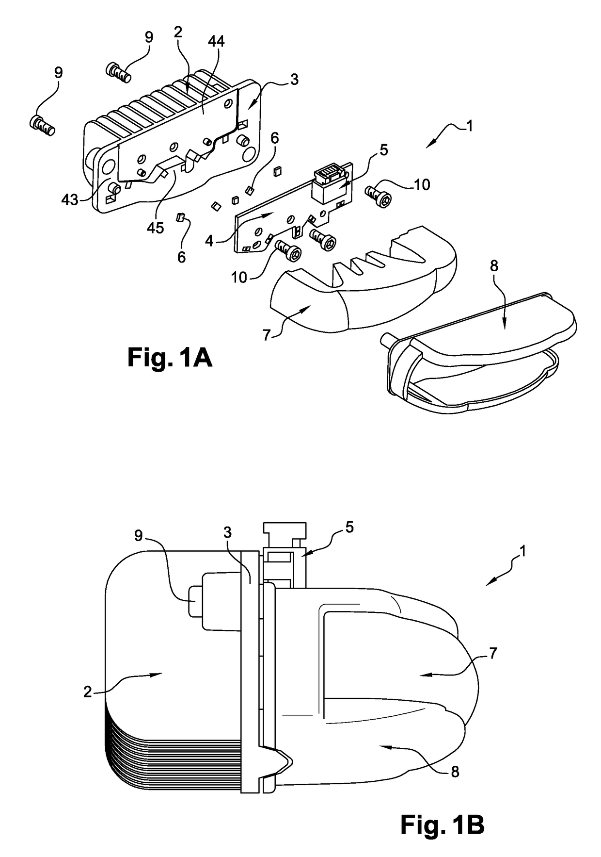
[0055]Referring to FIGS. 1A and 1B, a light module 1 according to the invention comprises a heat sink 2 linked to a substrate 3, an electronic card 4 provided with an electrical connector 5, five light-emitting diodes 6 which are called LEDs herein below in the description, a part 7 made of transparent material according to the invention and a protecting and securing housing 8, suitable for gripping the transparent part 7. The housing 8 is fixed to the substrate 3 by means of a first series of screws 9. The electronic card 4 is anchored in the substrate 3 by means of a second series of screws 10. Such a light module 1 is intended to be fixed, for example, inside a vehicle headlight.

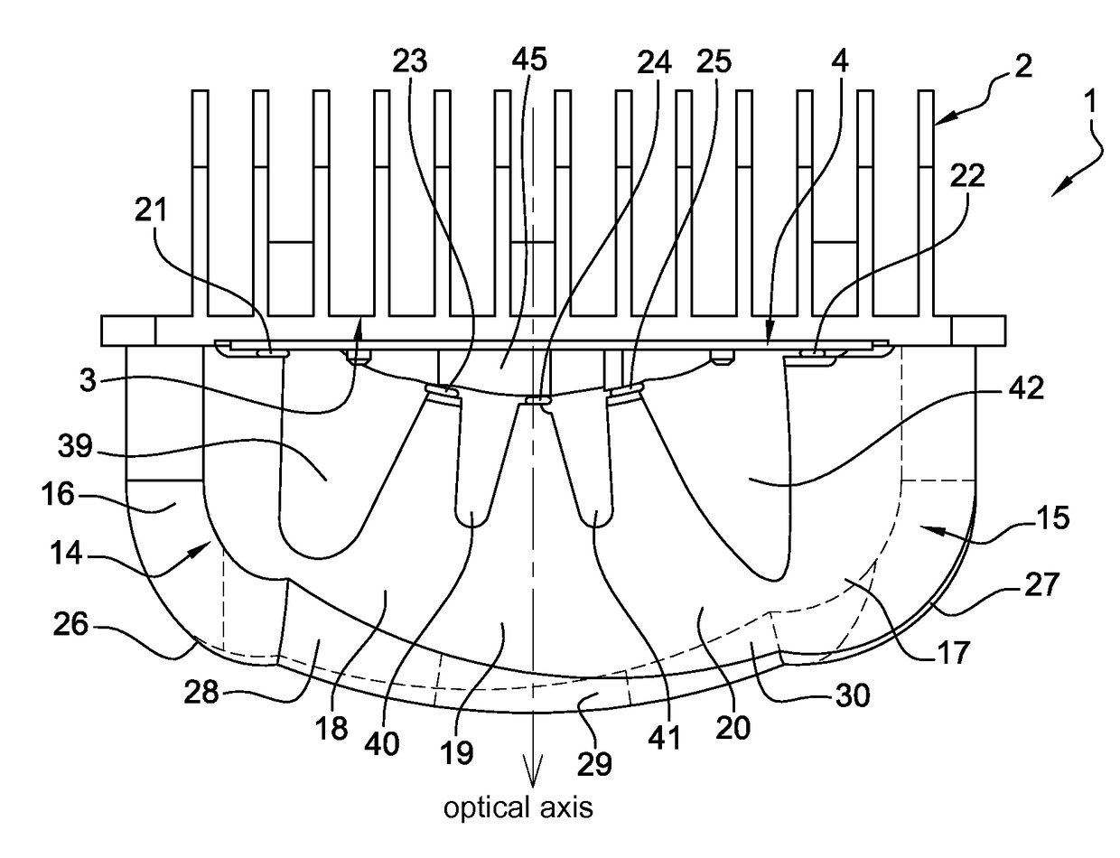
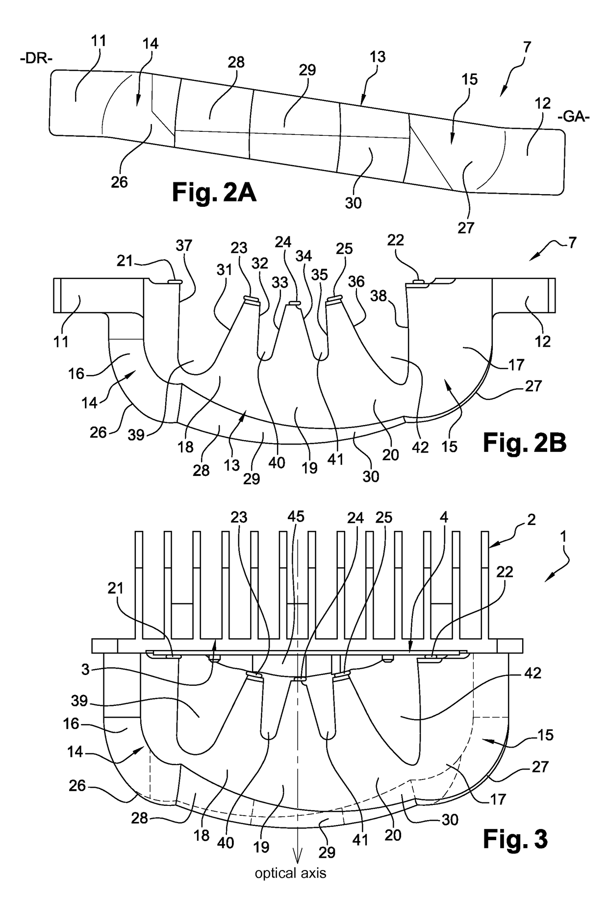
[0056]Referring to FIGS. 2A, 2B and 3, the transparent part 7 made of transparent material according to the invention is solid and is made of PVC (polyvinyl chloride), and acts as an optical lens. This transparent part 7 schematically comprises two lateral tabs 11, 12 and a central body 13 situated betwee...


PUM


Abstract

A part made of transparent material comprising at least two individual portions each consisting of an input surface and an output surface, the output surface being focused on the input surface of the same portion, the output surfaces being contiguous so as to form an overall output surface of the part which is continuous. Furthermore, the input surfaces are separated at a distance from one another in order to prevent rays from a light source placed on the input surface of a portion from being able to pass through the output surface of the adjacent individual portion.

Description

CROSS-REFERENCE TO RELATED APPLICATIONS[0001]This application claims priority to the French application 1458689 filed on Sep. 16, 2014, which application is incorporated herein by reference and made a part hereof.BACKGROUND OF THE INVENTION[0002]1. Field of the Invention[0003]The invention relates to a vehicle lighting device using a multiple-source optical lens.[0004]2. Description of the Related Art[0005]Lighting devices intended to be mounted in vehicle headlights exist and have already been the subject of patents. The patent application U.S. 2007 / 0120137, which is now issued as U.S. Pat. No. 7,560,742 can for example be cited, which relates to a multiple-source lighting device comprising a multiplicity of individual and distinct assemblies. Each assembly comprises a light source which is mounted on a substrate supplying current to the source, and a lens associated with the source. All the light emitted by this light source is transmitted to an output diopter of the lens, via a d...

Claims


Application Information

Patent Timeline
Patent Type & Authority Patents(United States)
IPC IPC(8): F21S41/20F21W107/10
CPCF21S41/24F21S41/141F21S41/143F21S41/25F21S41/19F21S41/265F21S41/27F21S41/14F21S45/47F21S41/29F21V5/045F21S41/151F21S41/26F21S41/663F21S43/14F21S43/26F21S43/27F21S45/48F21S43/19F21S43/241F21S43/243F21S43/249
Inventor MEYRENAUD, JEAN-LUC
Owner VALEO VISION SA
Why Eureka
Try Eureka