
Image compression system for dynamically adjusting compression parameters by content sensitive detection in video signal

a compression system and video signal technology, applied in the field of image compression, can solve the problems of inadequacies of inability to adapt to hardware implementation of real-time compression, and increased power, bandwidth and timing rate of data transmission, so as to save computation and reduce the related data stream and time delay

Active Publication Date: 2018-01-30
FOCALTECH SYST CO LTD
View PDF14 Cites 0 Cited by
  • Summary
  • Abstract
  • Description
  • Claims
  • Application Information

AI Technical Summary

Benefits of technology

[0009]The object of the present invention is to provide an image compression system for dynamically adjusting compression parameters by content sensitive detection in video signal, which makes use of the previously generated history data in compression to predict the parameters, without having to analyze the data in a large block, so as to save the computation and reduce the related data stream and time delay thereby conforming to the real-time compression / decompression application.

Problems solved by technology

Accordingly, in case that there is no suitable compression or other technique provided at the front-end, the power, bandwidth and timing rate required for data transmission are inevitably increased.
However, in a hardware implementation, such technique has to first test multiple sizes of blocks in parallel and estimate the number of bits required for each combination, and then determine the segmentation on the blocks.
Thus, the hardware cost is too high and thus it is not appropriate for a hardware implementation of real-time compression / decompression.

Method used


Image

  • Image compression system for dynamically adjusting compression parameters by content sensitive detection in video signal
  • Image compression system for dynamically adjusting compression parameters by content sensitive detection in video signal
  • Image compression system for dynamically adjusting compression parameters by content sensitive detection in video signal

Examples


Embodiment Construction

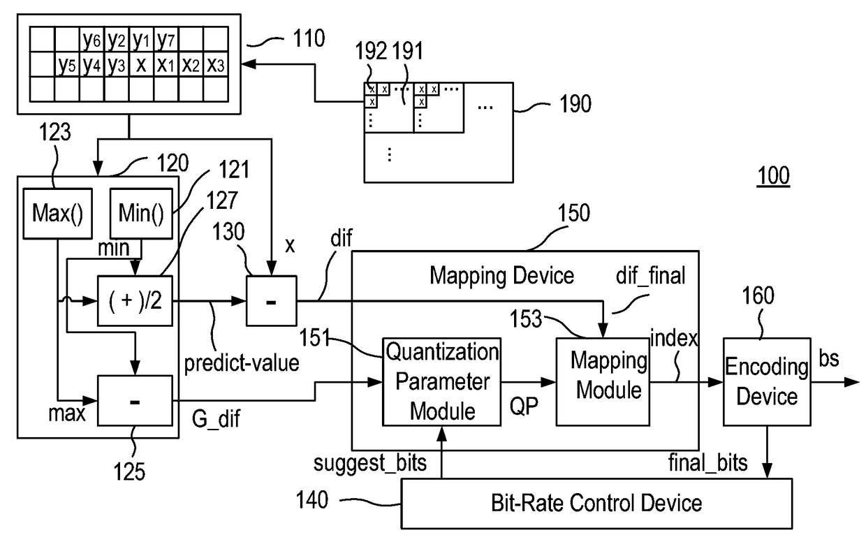
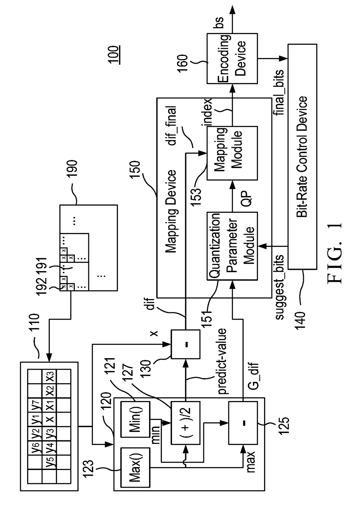
[0026]FIG. 1 is a block diagram of an image compression system 100 for dynamically adjusting compression parameters by content sensitive detection in video signal according to an embodiment of the present invention. The image compression system 100 is provided to encode a plurality of pixels 192 of a frame 190. The frame 190 has a plurality of blocks arranged in a matrix form, and each block has a plurality of pixels 192 arranged as a 16×8, 8×16, 8×8, 8×4, 4×8, or 4×4 matrix. The image compression system 100 includes a register 110, a sensitive detection device 120, a prediction difference device 130, a bit-rate control device 140, a mapping device 150, and an encoding device 160.

[0027]The register 110 temporarily stores the plurality of pixels 192 of the frame 190. The plurality of pixels 192 include a current encoding pixel (x), a plurality of historical decoded pixels, and a plurality of uncoded pixels. The historical decoded pixels include first to seventh historical decoded pix...


PUM


Abstract

An image compression system includes a register, a sensitive detection device, a prediction difference device, a bit-rate control device, a mapping device, and an encoding device, The register temporarily stores plural pixels, which have a current encoding pixel and plural historical decoded pixels. The sensitive detection device analyzes contents of the historical decoded pixels or a previous history data to calculate a prediction value and a current history data. The prediction difference device subtracts the prediction value from the current encoding pixel to generate a prediction difference value. The bit-rate control device adjusts a compression ratio according to a final bits signal so as to output a suggestion bits signal. The mapping device outputs an index based on the prediction difference value, the current history data, and the suggestion bits signal. The encoding device encodes the index to output a bit stream and the final bits signal.

Description

BACKGROUND OF THE INVENTION[0001]1. Field of the Invention[0002]The present invention relates to the technical field of image compression and, more particularly, to an image compression system for dynamically adjusting compression parameters by content sensitive detection in video signal.[0003]2. Description of Related Art[0004]With the rapid advance of electronics technologies and transmission techniques, the requirement for image quality in browsing is getting higher. Because the size of image data is usually huge, the image data is typically compressed for then being transferred to the Internet or stored in a hard disk. With image compression techniques, the memory space occupied by image data can be saved and the speed of transmission can thus be increased. Therefore, the image compression is currently very popular on research.[0005]In March, 2003, the video compression standard H.264 is formally published by the ITU-T / ISO, which is known as a new-generation video encoding stand...

Claims


Application Information

Patent Timeline
Patent Type & Authority Patents(United States)
IPC IPC(8): H04N19/176H04N19/154H04N19/146H04N19/124H04N19/14
CPCH04N19/146H04N19/124H04N19/176H04N19/154H04N19/14
Inventor HUANG, CHENG-PINHUANG, YA-CHEN
Owner FOCALTECH SYST CO LTD
Learn More