
Display device

a technology of display device and display panel, which is applied in the field of display device, can solve the problems of reducing the display quality the lcd device is unable to reach the current trend of thickness reduction, and the lcd device is unable to reach the full plane design of the lcd panel, so as to achieve the effect of reducing the thickness

Active Publication Date: 2018-02-06
CORETRONIC
View PDF13 Cites 0 Cited by
  • Summary
  • Abstract
  • Description
  • Claims
  • Application Information

AI Technical Summary

Benefits of technology

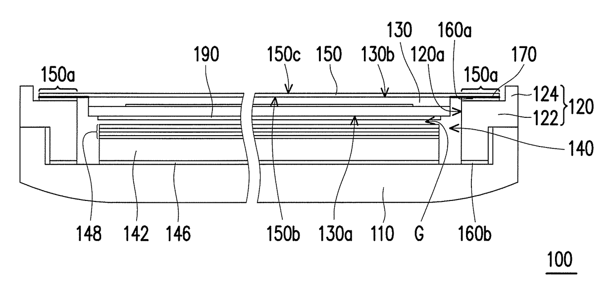
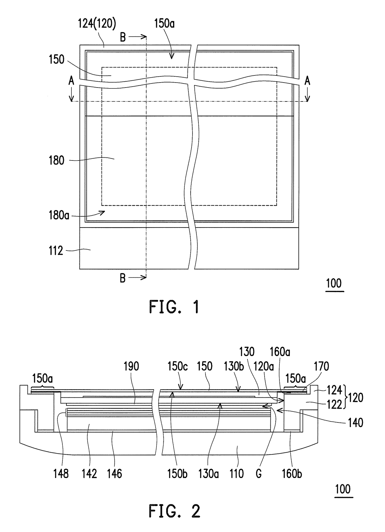
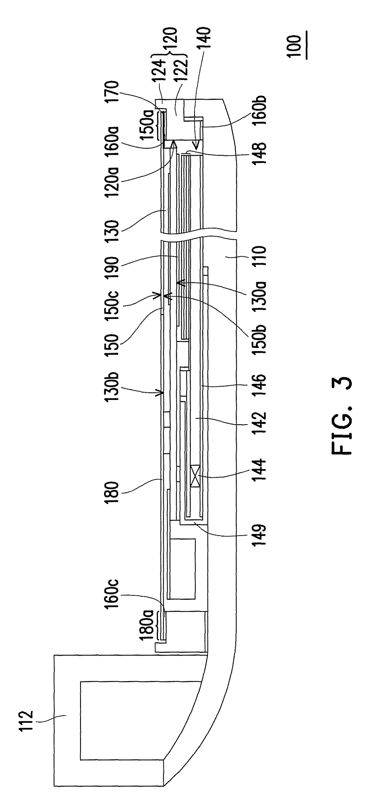
This invention is about a display device that prevents light from leaking at the edges of the display panel and reaches a full design on the panel. The invention also decreases the overall thickness of the display device. A first polarizer is extended from the display panel to the frame and carried by the frame, covering the edges of the display panel. The frame surrounds the first polarizer to protect it from damage. By using the first polarizer to cover the edges of the display panel, it avoids damaging the overall design of the display device. The display device also omits the conventional cover glass, making it thinner.

Problems solved by technology

However, the aforementioned LCD device is unable to reach the current trend of thickness reduction due to configuration of the cover glass or the plug-in touch panel.
However, when the cover glass is omitted to further decrease the thickness of the LCD device, the configuration method of omitting the cover glass is liable to result in a fact that the light beam emitted by the backlight module produces a light leakage phenomenon at the edge of the LCD panel, which decreases a display quality of the LCD panel.
However, based on the above solution, the LCD device is unable to reach a full plane design at the LCD panel.

Method used


Image

  • Display device
  • Display device
  • Display device

Examples


Embodiment Construction

[0023]In the following detailed description of the preferred embodiments, reference is made to the accompanying drawings which form a part hereof, and in which are shown by way of illustration specific embodiments in which the invention may be practiced. In this regard, directional terminology, such as “top,”“bottom,”“front,”“back,” etc., is used with reference to the orientation of the Figure(s) being described. The components of the present invention can be positioned in a number of different orientations. As such, the directional terminology is used for purposes of illustration and is in no way limiting. On the other hand, the drawings are only schematic and the sizes of components may be exaggerated for clarity. It is to be understood that other embodiments may be utilized and structural changes may be made without departing from the scope of the present invention. Also, it is to be understood that the phraseology and terminology used herein are for the purpose of description an...


PUM

PropertyMeasurementUnit
elasticaaaaaaaaaa
thicknessaaaaaaaaaa
external forceaaaaaaaaaa

Abstract

A display device including a back cover, a frame, a display panel, a backlight module and a first polarizer is provided. The frame is disposed on the back cover and has an opening. The display panel is disposed in the opening and has a first surface and a second surface opposite to each other. The backlight module is disposed between the back cover and the display panel, where the first surface faces the backlight module. The first polarizer is disposed on the second surface, where a periphery of the first polarizer extends to the outside of the second surface and is carried by the frame, and the frame surrounds the periphery of the first polarizer. The display device avoids a light leakage phenomenon occurred at an edge of the display panel, achieves a full plane design at the display panel, and decreases a whole thickness.

Description

CROSS-REFERENCE TO RELATED APPLICATION[0001]This application claims the priority benefit of China application serial no. 201510475905.9, filed on Aug. 6, 2015. The entirety of the above-mentioned patent application is hereby incorporated by reference herein and made a part of this specification.BACKGROUND OF THE INVENTION[0002]Field of the Invention[0003]The invention relates to a display device, and particularly relates to a display device having a backlight module.[0004]Description of Related Art[0005]Along with quick development of the semiconductor industry and related electronics industry, digital display devices such as smart phones, notebooks, tablet PCs, flat-screen TVs are all developed towards a trend of more convenience, multi-function and good-looking. When these products are used, a display screen is an indispensable display interface, and a liquid crystal display (LCD) device has become a main stream of the display screens. Since a LCD panel of the LCD device is not lu...

Claims


Application Information

Patent Timeline
Patent Type & Authority Patents(United States)
IPC IPC(8): G02F1/1333G02F1/1335F21V8/00G06F3/041
CPCG02F1/133308G02B6/0055G02B6/0088G06F3/0412G02F1/133528G02F2001/133562G02F1/13338G02F2001/133317G02F1/133531G02F1/133317G02F1/133562
Inventor HSU, JENG-BINHSU, CHUN-CHI
Owner CORETRONIC
Learn More