Vent structure and electronic apparatus therewith

a technology of electronic equipment and vent structure, which is applied in the direction of lighting and heating equipment, electric equipment casings/cabinets/drawers, heating types, etc., can solve the problems of reducing the fluidity and heat dissipation efficiency of heat dissipation air flow, loud noise, and reducing heat dissipation, so as to improve the rotation agility of the louver and reduce noise.

Active Publication Date: 2018-02-06
WISTRON CORP
View PDF7 Cites 5 Cited by
  • Summary
  • Abstract
  • Description
  • Claims
  • Application Information

AI Technical Summary

Benefits of technology

[0005]An objective of the invention is to provide a vent structure for a unidirectional flow. A louver of the vent structure is structurally simple and can be made of light material, which is conducive to improving the rotation agility of the louver and reducing the noise probably produced when in operation.
[0007]Another objective of the invention is to provide an electronic apparatus having the vent structure of the invention. The electronic apparatus uses the vent structure to prevent any air flow outside the electronic apparatus from entering the interior of the electronic apparatus and interfering with any internal air flow such as heat dissipation air flows. Similarly, the louver of the vent structure is structurally simple and can be made of light material, which is conducive to improving the rotation agility of the louver and reducing the noise probably produced when in operation.
[0009]Compared with the prior art, the vent structure of the invention has the structurally simple louver. The louver can be made of light materials, for example by folding a plastic thin sheet (e.g. a sheet of Mylar with a thickness of 0.05 mm), binding the folded portions, and inserting a thin metal rod through the bent portion of the plastic thin sheet. The structure of the louver is conducive to improving the rotation agility of the louver and reducing the noise probably produced when in operation.

Problems solved by technology

If the vent is not provided with any device capable of closing the vent, when the fan fails or shuts down, an air flow outside the electronic apparatus may enter the electronic apparatus through the vent and interfere with other air flows generated inside the electronic apparatus by other fans leading to a reduction to heat dissipation.
Because the metal sheet is usually relatively heavy and the injection part is usually relatively thick, the louver has a certain weight so that it is not easy for a heat dissipation air flow in the interior of the electronic apparatus to move the louver, which reduces the fluidity and heat dissipation efficiency of the heat dissipation air flow.
Furthermore, when the louver is open, the heat dissipation air flow blows the louver continuously leading to a loud noise.

Method used


Image

  • Vent structure and electronic apparatus therewith
  • Vent structure and electronic apparatus therewith
  • Vent structure and electronic apparatus therewith

Examples


Embodiment Construction

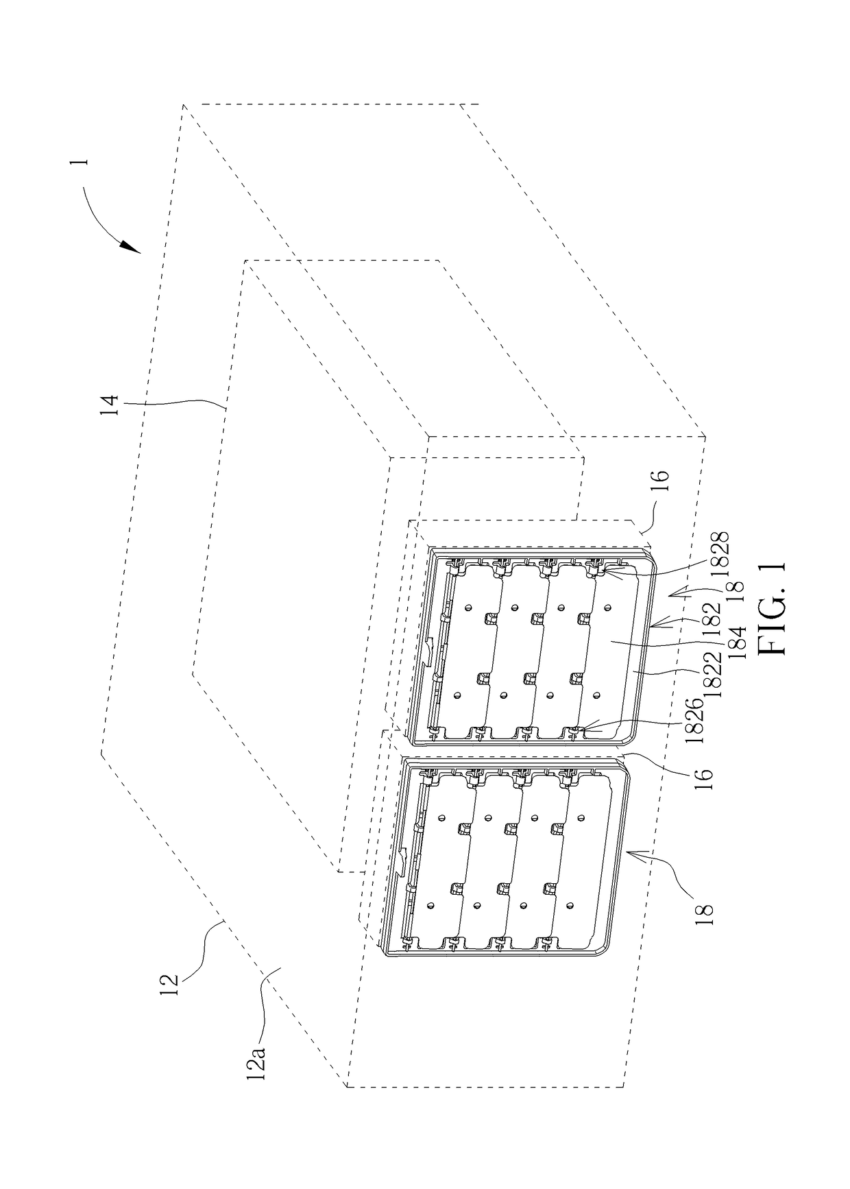
[0021]Please refer to FIG. 1 that is a schematic diagram illustrating an electronic apparatus 1 of an embodiment according to the invention. The electronic apparatus 1 includes a casing 12, an electronic device 14, two fans 16, and two vent structures 18; therein, the casing 12, the electronic device 14, and the fans 16 are shown by their profiles in dashed lines. The casing 12 forms an accommodating space 12a. The electronic device 14 is disposed in the accommodating space 12a. The two vent structures 18 are disposed adjacent to each other on the casing 12. The two fans 16 are disposed adjacent to the two vent structure 18 respectively. The vent structures 18 allow air flows to flow through only in one direction, so that an air flow generated by the fan 16 can flow out of the casing 12 through the corresponding vent structure 18 and the vent structures 18 can prevent any air flow outside the casing 12 from entering the casing 12 through the vent structures 18.

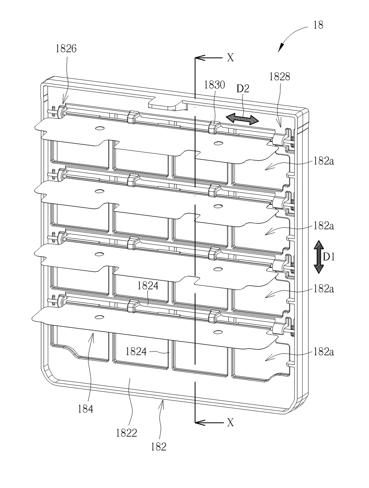
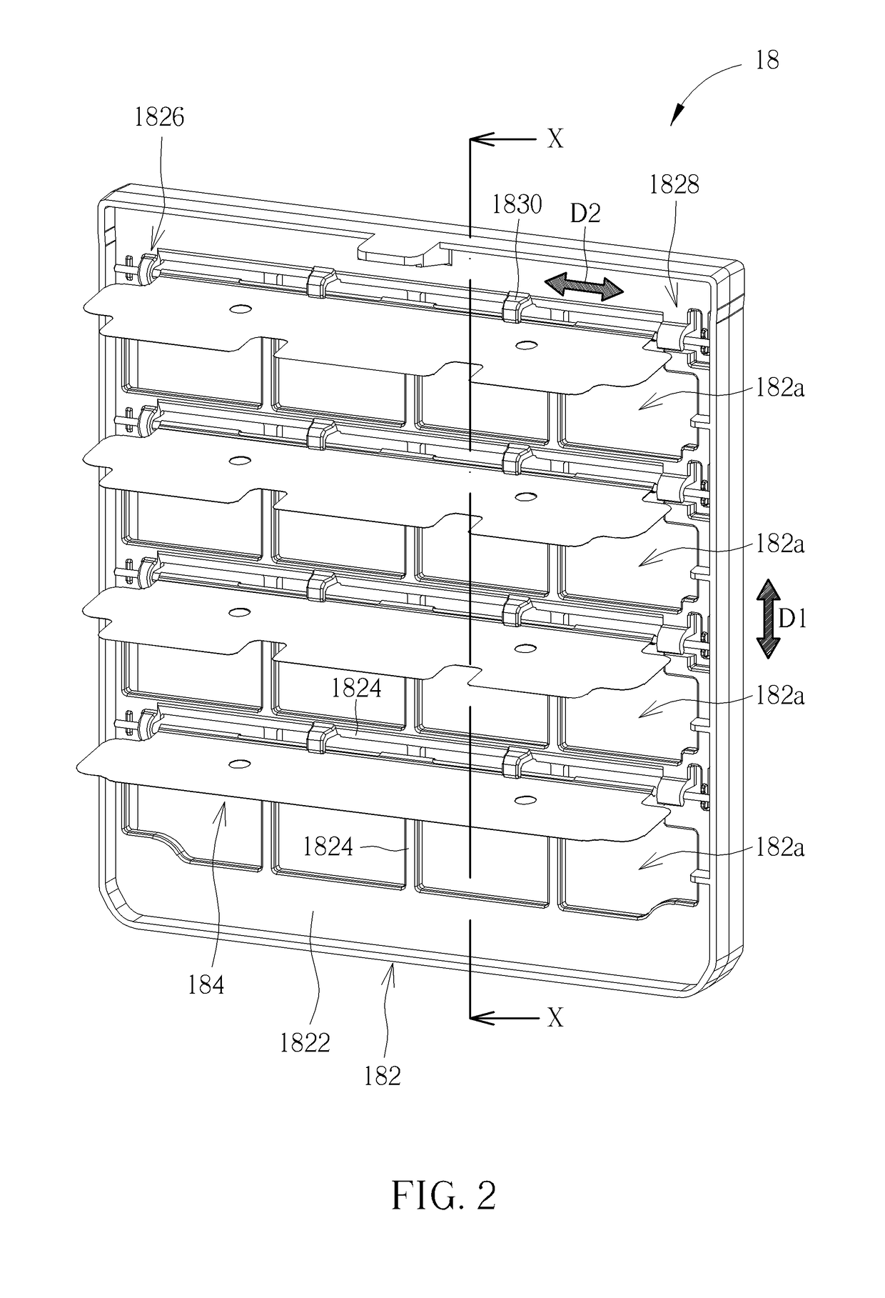
[0022]Please also refe...


PUM


Abstract

An electronic apparatus includes a casing, a vent structure on the casing, and an electronic device inside the casing. The vent structure is used for a unidirectional flow and includes a frame and a louver. The louver includes a sheet body and a shaft. The sheet body includes a bent portion, a first and a second portion which oppositely extend from the bent portion and bind together. The shaft passes through a through hole formed by the bent portion and is connected to the frame, so that the sheet body is rotatable. When the louver is located at a closed position, the sheet body covers at least a portion of an opening structure of the frame. The louver is structurally simple and can be made of light material, which is conducive to improving the rotation agility of the louver and reducing the noise probably produced when in operation.

Description

BACKGROUND OF THE INVENTION[0001]1. Field of the Invention[0002]The invention relates to a vent structure and an electronic apparatus, and especially relates to a vent structure for a unidirectional flow and an electronic apparatus having the vent structure.[0003]2. Description of the Prior Art[0004]Conventional electronic apparatuses usually have a heat dissipation system that uses a fan to generate an air flow that flows out of the electronic apparatus from the interior of the electronic apparatus through a vent on the casing of the electronic apparatus for heat dissipation to electronic devices inside. If the vent is not provided with any device capable of closing the vent, when the fan fails or shuts down, an air flow outside the electronic apparatus may enter the electronic apparatus through the vent and interfere with other air flows generated inside the electronic apparatus by other fans leading to a reduction to heat dissipation. For this problem, an electronic apparatus, pr...

Claims


Application Information

Patent Timeline
Patent Type & Authority Patents(United States)
IPC IPC(8): H05K5/00H05K7/20F24F13/14
CPCH05K7/20181F24F13/1426
Inventor LIU, QIWU, RONG-WEICHEN, TA-WEI
Owner WISTRON CORP
Why Eureka
Try Eureka