Particle beam irradiation apparatus

a particle beam and irradiation apparatus technology, applied in radiation therapy, x-ray/gamma-ray/particle irradiation therapy, therapy, etc., can solve the problem of patient ct data error, patient fixed position error, and actual dose distribution not matched to target distribution

Active Publication Date: 2018-02-13
HITACHI LTD
View PDF18 Cites 0 Cited by
  • Summary
  • Abstract
  • Description
  • Claims
  • Application Information

AI Technical Summary

Benefits of technology

[0020]According to the particle beam irradiation apparatus of the invention, at the second or later time of radiation, the particle beam is interrupted based on the corrected dose value resulted from subtracting the value of the excessive dose at the previous time at that irradiation position from the value of the divisional target dose, so that it is possible to significantly reduce, in the spot scanning method, the total amount of plural times of excessive doses due to delay of beam interruption.

Problems solved by technology

According to the respective scanning irradiation methods mentioned above, because various uncertainties exist in actual irradiation, there is a possibility that, although the target distribution must be obtained on a calculation basis, the dose distribution actually obtained is not matched to the target distribution.
The uncertainties include, for example, instability in intensity and / or position of the particle beam, an error in patient fixed position, an error in patient CT data, a signal delay and / or a noise of a control device, and the like.
Further, in the case where a tumor exists, in particular, in a respiratory organ, such as a liver, a lung, or the like, because the position of the tumor, the state around the tumor, or the like, changes temporally due to breathing of the patient, so that it is difficult to give a dose as planned to the diseased site.

Method used


Image

  • Particle beam irradiation apparatus
  • Particle beam irradiation apparatus
  • Particle beam irradiation apparatus

Examples


embodiment 1

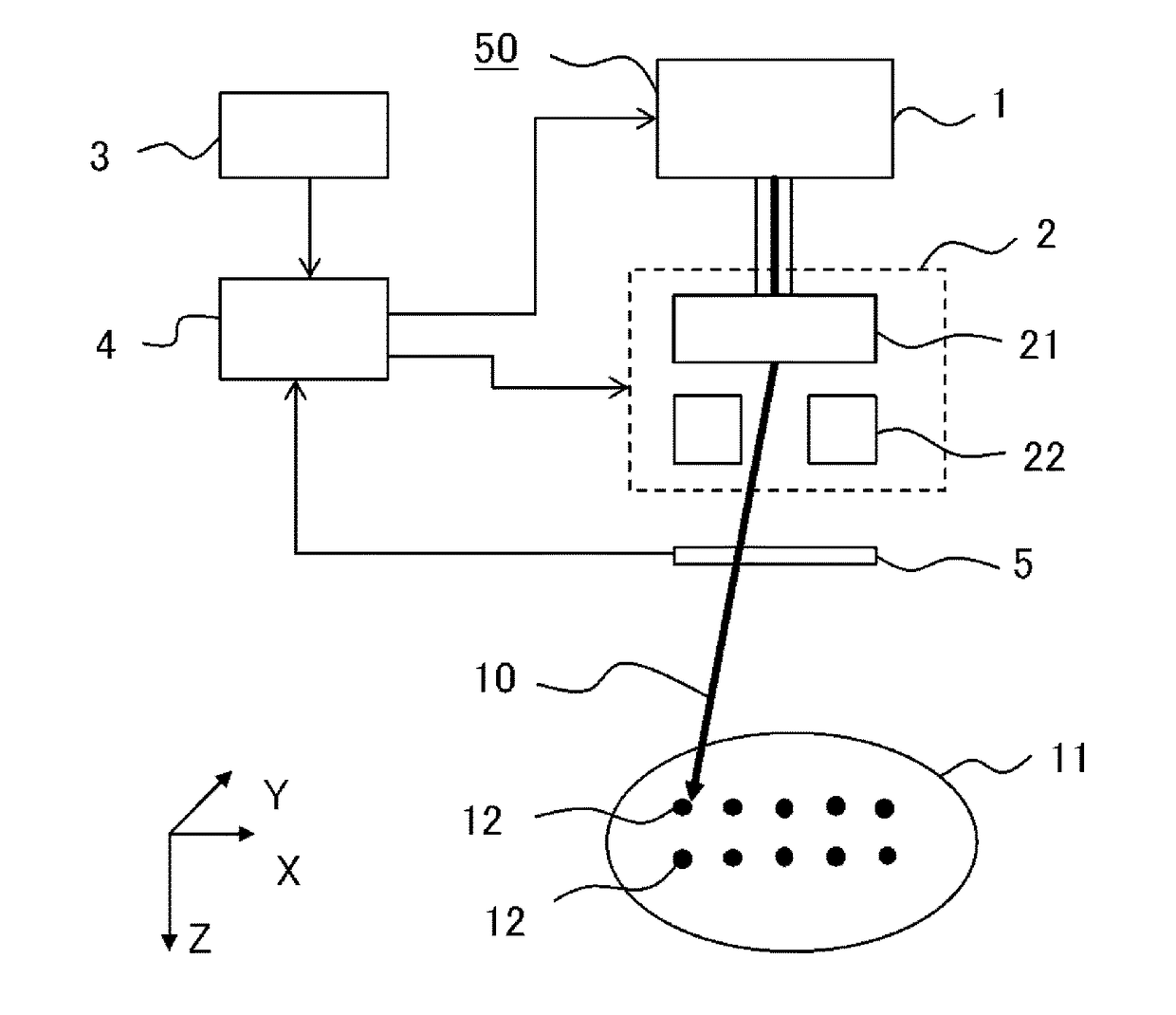
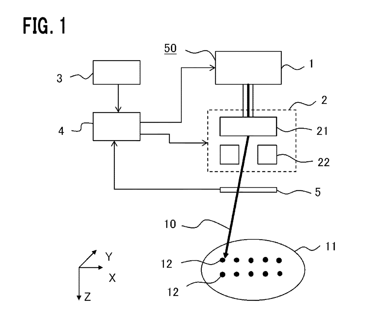
[0034]FIG. 1 is a schematic configuration diagram of a particle beam irradiation apparatus according to Embodiment 1 of the invention.

[0035]A particle beam irradiation apparatus 50 according to Embodiment 1 of the invention includes: a particle beam generation-transportation system 1 that accelerates charged particles up to a required energy to thereby generate accelerated charges particles as a particle beam 10, and then transports it to a scanning device 2; and the scanning device 2 that deflects the particle beam 10 generated by the particle beam generation-transportation system 1 in two directions perpendicular to a Z-direction that is a traveling direction of the particle beam, namely, X and Y-directions, to thereby causing the beam to scan at arbitrary positions in a patient's tumor, that is, an irradiation target 11. Generally, the particle beam generation-transportation system 1 includes an accelerator for accelerating the charged particles and a transport system for transpo...

embodiment 2

[0054]In Embodiment 1, description has been made about a configuration example of the storage unit 3 with the assumption that the total dose to be radiated to each irradiation position 12 is equally divided by the number of total rescan times. However, if it is intended to make the divisional target dose value that is the value of the target dose per one time, different each time for every number of rescans, it is impossible to get this by the configuration of the storage unit 3 as shown in FIG. 4 and FIG. 5. In Embodiment 2, a configuration example of the storage unit 3 that can make the divisional target dose value different each time for every number of rescans, will be described.

[0055]FIG. 6 is a table briefly illustrating an example of information stored in a storage unit according to Embodiment 2 of the invention, and FIG. 7 is a table briefly illustrating an example of information during irradiation stored in the storage unit according to Embodiment 2 of the invention. It is ...

embodiment 3

[0059]The configuration of the storage unit 3 may be other than the configurations in Embodiment 1 and Embodiment 2.

[0060]FIG. 8 is a table briefly illustrating an example of information stored in a storage unit according to Embodiment 3 of the invention, and FIG. 9 is a table briefly illustrating an example of information during irradiation stored in the storage unit according to Embodiment 3 of the invention. It is assumed that, in the storage unit 3 of Embodiment 3, there are reserved memory regions for storing an irradiation position number, a target dose per one time of rescan (divisional target dose) and a corrected dose as a revised target dose, for every irradiation position 12, and in the initial state before radiation, as each value in “Corrected Dose”, a value that is the same as the target dose value per one time of scan (divisional target dose) is stored. Shown in FIG. 8 and FIG. 9 are examples for the irradiation position number from 1 to m. As shown in initial-state m...


PUM


Abstract

A particle beam irradiation apparatus radiates a particle beam plural times per one irradiation position. A storage unit stores a dose to be radiated each of the times (divisional target dose). A dose monitor measures the dose of the particle beam radiated to the irradiation position. At the first time of radiation, a controller outputs an interruption signal when the dose measured by the dose monitor reaches the divisional target dose. The dose monitor measures a dose (excessive dose) radiated after the interruption signal is outputted until the particle beam is actually interrupted. Then, it is defined: Corrected Dose value=Divisional Target Dose−Excessive Dose Value. Instead, it may be defined: Corrected Dose value=Divisional Target Dose−Excessive Dose Estimation Value. At the second time of radiation, the controller outputs an interruption signal when the dose measured by the dose monitor reaches the corrected dose value.

Description

TECHNICAL FIELD[0001]The present invention relates to a particle beam irradiation apparatus that radiates a particle beam to a diseased site, such as a cancer, to thereby perform its treatment, which is a particle beam irradiation apparatus to be used for performing radiation of the particle beam with a specified dose in conformity with a three-dimensional shape of the diseased site.BACKGROUND ART[0002]A particle beam therapy is a method for treating a cancer in such a manner that charged particles, such as protons or carbon ions, are accelerated to about several hundreds mega electronvolts by use of a device, such as an accelerator, which are then radiated to a patient to thereby give a dose to a tumor in the body. At this time, for the tumor, it is important to form a dose distribution that is as close as possible to a dose distribution ordered by a doctor, namely, a target distribution. In many cases, the target distribution is such a distribution in which the dose in the tumor i...

Claims


Application Information

Patent Timeline
Patent Type & Authority Patents(United States)
IPC IPC(8): A61N5/00A61N5/10
CPCA61N5/1071A61N5/10A61N5/1067A61N5/1077A61N5/1044A61N2005/1087
Inventor SAKAMOTO, YUSUKEPU, YUEHUHARADA, HISASHIHONDA, TAIZO
Owner HITACHI LTD
Why Eureka
Try Eureka