Capacitive fingerprint sensing device and method for capturing a fingerprint using the sensing device

a fingerprint sensing and capacitive technology, applied in the field of fingerprint sensing devices, can solve the problems of difficult fingerprint image capture, loss of resolution and image contrast, and difficulty in capturing fingerprint images at large finger-to-sensor distances, so as to reduce energy consumption and reduce the time it takes to capture fingerprint images. , the effect of enhancing the direct capacitive measurement method

Active Publication Date: 2018-02-20
FINGERPRINT CARDS ANACATUM IP AB
View PDF20 Cites 42 Cited by
  • Summary
  • Abstract
  • Description
  • Claims
  • Application Information

AI Technical Summary

Benefits of technology

[0015]The present invention is based on the realization that capacitive fingerprint sensing can be improved by providing a fingerprint sensing device capable of inducing an ultrasonic vibration potential in the finger by means of an electroacoustic transducer, thereby creating an electric potential which is detected by the at least one sensing structure. In existing technologies a potential is controllably introduced into the finger through a galvanic or capacitive coupling to the finger, such that the entire finger is placed at the same potential level. In contrast, the above described sensing device only induces a potential in an area of the finger which is in direct contact with the sensing surface, i.e. finger ridges, and which is excited by the focused ultrasonic beam. Consequently, the capacitive sensing signal is only provided by an area of the finger having the same size as the size of the focused ultrasound beam at the sensing surface, eliminating the contribution from the rest of the finger and thereby providing an improved signal to noise ratio since the influence from the overall background average noise is reduced.
[0044]The above described inventive concept is also applicable as an enhancement to existing capacitive fingerprint sensing technologies where non-acoustic means for potential generation in the finger are already used. Furthermore, the present invention opens up new opportunities relating to the sensing device architecture since these non-acoustic means for introducing a potential in the finger may be eliminated.

Problems solved by technology

This presents a challenging problem.
The source of this problem is not only related to weakening of the capacitive signal by increased finger-to-sensor distance.
However, a problem is related to the loss of resolution and image contrast as the finger-to-sensor distance is increased.
This is caused by the fact that distinguishing minute capacitance variations due to finger corrugations from a large background “average” that comes from the sum of all the ridges and valleys “visible” to a pixel becomes extremely difficult at large finger-to-sensor distances.
Alternatively, or in combination, the fingerprint sensing may be limited to certain areas of the touch sensitive display.

Method used


Image

  • Capacitive fingerprint sensing device and method for capturing a fingerprint using the sensing device
  • Capacitive fingerprint sensing device and method for capturing a fingerprint using the sensing device
  • Capacitive fingerprint sensing device and method for capturing a fingerprint using the sensing device

Examples


Embodiment Construction

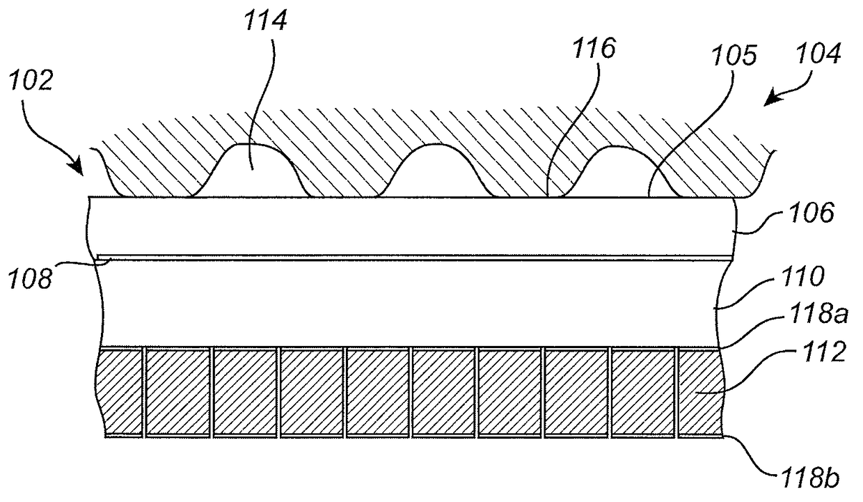
[0055]In the present detailed description, various embodiments of the system and method according to the present invention are mainly described with reference to a capacitive fingerprint sensing device suitable for being arranged in an electronic device such as a mobile phone. It should however be noted that various embodiments of the fingerprint sensing device may be adapted for use also in other applications.

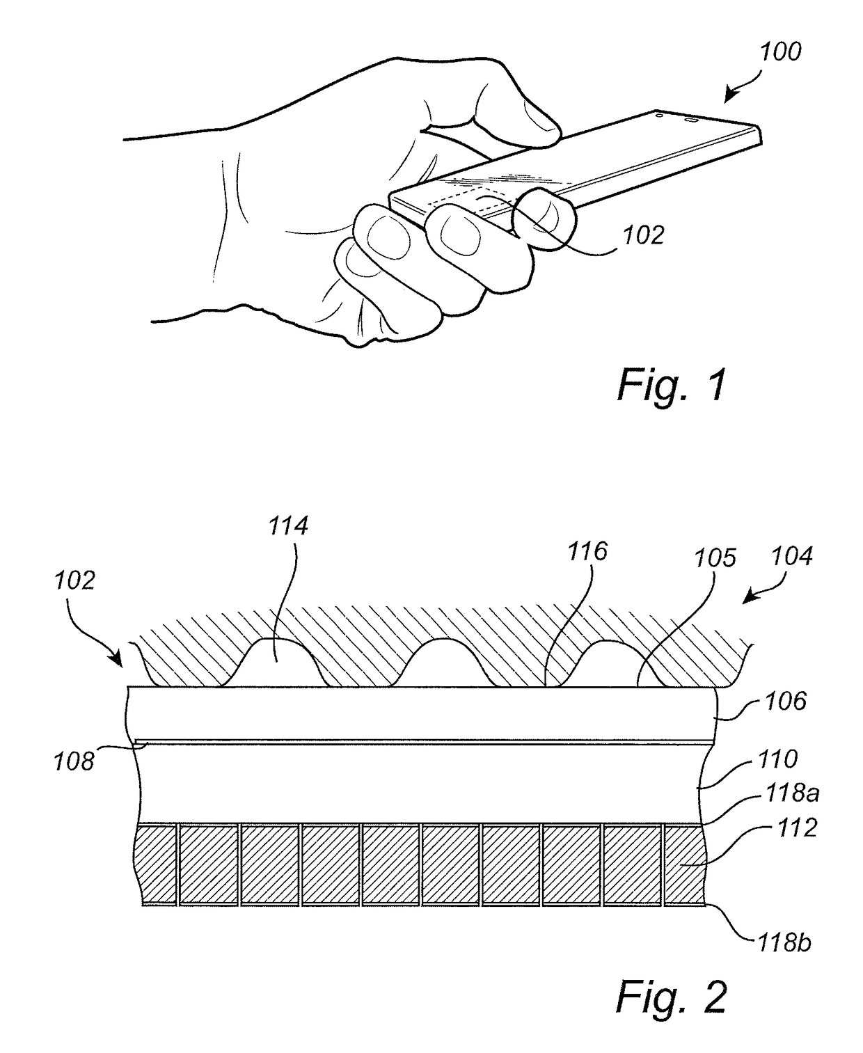
[0056]FIG. 1 schematically illustrates an application for a fingerprint sensing device 102 according to an example embodiment of the present invention, in the form of a mobile phone 100 with an integrated fingerprint sensing device 102. The fingerprint sensing device is illustrated here as being arranged underneath a cover glass of the mobile phone 100. The fingerprint sensing device 102 may also be arranged in a button, on the side or on a backside of a phone.

[0057]The fingerprint sensing device 102 may, for example, be used for unlocking the mobile phone 100 and / or for autho...


PUM


Abstract

There is provided a capacitive fingerprint sensing device for sensing a fingerprint pattern of a finger, the capacitive fingerprint sensing device comprising: a protective dielectric top layer having an outer surface forming a sensing surface to be touched by the finger; at least one electrically conductive sensing structure arranged underneath the top layer; readout circuitry coupled to the at least one electrically conductive sensing structure to receive a sensing signal indicative of a distance between the finger and the sensing structure; and a plurality of individually controllable electroacoustic transducers arranged underneath the top layer and configured to generate a focused ultrasonic beam, and to transmit the ultrasonic beam through the protective dielectric top layer towards the sensing surface to induce an ultrasonic vibration potential in a ridge of finger placed in contact with the sensing surface at the location of the ultrasonic beam.

Description

CROSS-REFERENCE TO RELATED APPLICATION[0001]The present application is based on and claims the benefit of Swedish patent application Serial No. 1650592-7, filed May 2, 2016, the content of which is hereby incorporated by reference in its entirety.FIELD OF THE INVENTION[0002]The present invention relates to a fingerprint sensing device. In particular, the present invention relates to a capacitive fingerprint sensing device comprising an electroacoustic transducer, and to a method for capturing a fingerprint using the sensing device.BACKGROUND OF THE INVENTION[0003]Various types of biometric systems are used more and more in order to provide for increased security and / or enhanced user convenience.In particular, fingerprint sensing systems have been adopted in, for example, consumer electronic devices, thanks to their small form factor, high performance, and user acceptance.[0004]Among the various available fingerprint sensing principles (such as capacitive, optical, thermal etc.), cap...

Claims


Application Information

Patent Timeline
Patent Type & Authority Patents(United States)
IPC IPC(8): G06K9/00G06F3/044G06V40/12G06V40/13G06V40/40
CPCG06K9/0002G06K9/00899G06K9/00087G06F3/044G06V40/1359G06V40/1382G06V40/1365G06V40/1306G06V40/40
Inventor GHAVANINI, FARZAN
Owner FINGERPRINT CARDS ANACATUM IP AB
Why Eureka
Try Eureka