Method of manufacturing piezoelectric microactuators having wrap-around electrodes

a piezoelectric microactuator and wrap-around electrode technology, which is applied in the direction of instruments, chemistry apparatus and processes, and record information storage, can solve the problems of difficult control of the top electrode, time-consuming and costly, and the method of bonding pzts, so as to simplify the assembly process and the final electrical connection, simplify the assembly process, and simplify the effect of the final electrical connection

Active Publication Date: 2018-03-06
MAGNECOMP
View PDF47 Cites 6 Cited by
  • Summary
  • Abstract
  • Description
  • Claims
  • Application Information

AI Technical Summary

Benefits of technology

[0013]In a second aspect of the invention, the invention is of a method for producing a PZT microactuator or other electronic device having a wrap-around electrode, and of applying and using such a device. The wrap-around electrode is a conductive coating that wraps around at least part of the PZT to cover more than one face of the PZT, and thus conduct electricity to the opposite face. The wrap-around electrode simplifies both the assembly process and the final electrical connection(s) to the PZT in the completed suspensions. According to the method, a central electrode is first formed such as by sputtering on a first face of a wafer of piezoelectric material. A first side electrode on then formed on a first side or end of the wafer and over the adjacent edge, such that the first electrode extends onto the first face but is electrically not connected with, i.e., is discontinuous from, the central electrode on that face. Similarly, a second side electrode is also formed on a second side or end that is opposite the first side, with the second electrode also extending over an adjacent edge, such that the second electrode extends onto the first face but is also electrically discontinuous from the central. Conductive material is then deposited such as but sputtering on the second face of the wafer opposite the first face, with that conductive material extending to and being in electrical contact with the first and second side electrodes. The wafer now has one central electrode on the first face that covers most of the first face, and two side electrodes, with each side electrode covering not only its respective side but wrapping around that side and covering at least respective parts of the first and second faces, preferably at narrow respective strips on the first face on either side of the central electrode. The wafer is then cut in half. The result is two piezoelectric devices, each device having a wrap-around electrode such that the first face includes both electrodes. Both the drive and the ground connection can therefore both be made to the first face of the PZT, thus simplifying the electrical connections to it.
[0014]The invention simplifies the assembly process for a DSA suspension, and eliminates contamination sources in the sensitive final suspension assembly.

Problems solved by technology

In general, the height of the conductive epoxy 322 for the top electrode is difficult to control, and the overall PZT attachment process requires three epoxy bonding steps, which is time consuming and costly.
There are drawbacks to the prior methods of bonding PZTs to suspensions.
It can be difficult to control exactly how much epoxy is dispensed, where the adhesive ends up due to flow of the liquid adhesive, and other issues.
Additionally, if the PZT is located at or near the gimbal which carries the magnetoresistive read / write head, it becomes critical to be able to predict and control the flow of adhesive because differences in adhesive flow and distribution from one part to another can adversely affect the geometries, mechanical properties, and resulting performance of the suspension.
These issues are particularly pronounced when the PZT is located at a particularly sensitive part of the suspension such as near or at the gimbaled head slider.
Still further, the presence of liquid epoxy and its dispensing equipment within the final assembly room represents both a potential source of contamination, as well as an additional and expensive manufacturing step.
Another drawback to the prior attachment means is the delays in assembly time required for multiple rounds of epoxy, including both conductive epoxy and non-conductive epoxy, to be dispensed and then cured. FIG. 6. illustrates the typical manufacturing process for PZT attachment, in which liquid epoxy is applied to the PZT, the interconnect, and / or the load beam before attaching the PZT.

Method used


Image

  • Method of manufacturing piezoelectric microactuators having wrap-around electrodes
  • Method of manufacturing piezoelectric microactuators having wrap-around electrodes
  • Method of manufacturing piezoelectric microactuators having wrap-around electrodes

Examples


Embodiment Construction

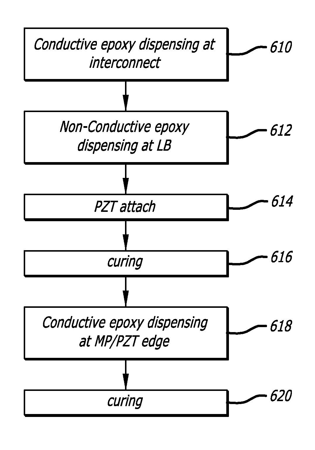
[0038]A first aspect of the invention is the use of adhesive film to attach the PZT to the suspension. FIG. 7 illustrates the method. Conductive epoxy is dispensed at the interconnect (710). The PZT having the integrated adhesive film or other B-staged adhesive is then attached to the suspension (712), and the adhesive is then cured (714). Conductive epoxy is then dispensed at (716) and cured (718). The step of epoxy dispensing on the load beam is eliminated by using a PZT with integrated adhesive film. PZT with integrated adhesive film can be manufactured with either laminated adhesive film on it at the PZT wafer level or by printing or by a wafer backside coating process as used in the semiconductor industry. Because the adhesive film is attached to the PZT at the wafer level before dicing into individual PZT dies, process simplification and cost savings can be achieved. Also, tight control of the adhesive thickness can be achieved. As shown in FIG. 7 the use of a PZT with integra...


PUM

PropertyMeasurementUnit
piezoelectricaaaaaaaaaa
conductiveaaaaaaaaaa
electrical connectivityaaaaaaaaaa

Abstract

A method of manufacturing a piezoelectric microactuator having a wrap-around electrode includes forming a piezoelectric element having a large central electrode on a top face, and having a wrap-around electrode that includes the bottom face, two opposing ends of the device, and two opposing end portions of the top face. The device is then cut through the middle, separating the device into two separate piezoelectric microactuators each having a wrap-around electrode.

Description

CROSS-REFERENCE TO RELATED APPLICATIONS[0001]This application is a continuation of U.S. patent application Ser. No. 14 / 045,773 filed Oct. 3, 2013, which claims priority from Provisional Patent Application No. 61 / 709,573 filed Oct. 4, 2012, the disclosures of which are incorporated by reference as if fully set forth herein.BACKGROUND OF THE INVENTION1. Field of the Invention[0002]This invention relates to the field of suspensions for hard disk drives. More particularly, this invention relates to a method of manufacturing piezoelectric microactuators having wrap-around electrodes such as for use in dual stage actuated (DSA) disk drive suspensions.2. Description of Related Art[0003]Magnetic hard disk drives and other types of spinning media drives such as optical disk drives are well known. FIG. 1 is an oblique view of an exemplary prior art hard disk drive and suspension for which the present invention is applicable. The prior art disk drive unit 100 includes a spinning magnetic disk ...

Claims


Application Information

Patent Timeline
Patent Type & Authority Patents(United States)
IPC IPC(8): H01L41/297B32B38/18G11B5/48H01L41/33B32B37/12
CPCH01L41/297H01L41/33B29C2793/0027G11B5/48B32B38/185B32B37/1207G11B21/106G11B5/4873Y10T156/10B29C2793/0036Y10T156/1052H10N30/073H10N30/06B32B38/0036G11B5/56B32B37/1292G11B21/10G11B5/5552B32B37/04B32B38/10G11B5/483B32B2038/0076Y10T29/42H10N30/088G11B5/4806G11B5/4846G11B5/4853
Inventor HAHN, PETEREE, KUEN CHEEZHANG, LONG
Owner MAGNECOMP
Why Eureka
Try Eureka