Rotorcraft top fairing fitted with a movable member for guiding a stream of air flowing towards the rear of the rotorcraft

a technology of rotorcraft and rear end, applied in the field of fairing, can solve the problems of chaotic turbulence generated at the rear end of the fairing, the stability of the rotorcraft in yaw is affected, and the solution is not fully satisfactory for optimizing, so as to achieve the desired dynamic range and effect of optimizing

Active Publication Date: 2018-03-13
EUROCOPTER
View PDF7 Cites 1 Cited by
  • Summary
  • Abstract
  • Description
  • Claims
  • Application Information

AI Technical Summary

Benefits of technology

[0031]Guiding the first stream of air by the movable member serves to deflect the first stream of air towards the sides of the rotorcraft so as to avoid a flow of the first stream of air towards the rear of the rotorcraft along its longitudinally-extending direction.
[0051]However, it appears that such a solution could be improved in order to optimize the sought-after dynamic range and effectiveness in the guidance of the first stream of air towards the rear of the rotorcraft.

Problems solved by technology

It has nevertheless been found that such a solution is not fully satisfactory for optimizing stabilization of the rotorcraft in the event of a side wind and / or of the rotorcraft sideslipping in yaw, in particular for light rotorcraft where it is desired to enhance their maneuverability in flight.
In particular, it is necessary to avoid the flow of air along the fairing giving rise to instabilities in maintaining a flight path and / or to disturbances in yaw attitude control of the rotorcraft.
It is found that when the flow of air around the rotorcraft includes a significant sideways vector component, the regularity of the flow of said turbulence towards the rear of the fairing is disturbed, and consequently the stability of the attitude of the rotorcraft in yaw is affected thereby.
More particularly, the turbulence generated at the rear end of the fairing tends to become chaotic with frequency spreading and also tends to move rearwards, potentially impacting against the rear aerodynamic portions.
Such instability in the flow of the turbulence, which is made worse in the event of a side wind and / or of the rotorcraft sideslipping in yaw, has the effect of producing unwelcome vibration that may harm the mechanical strength of the rotorcraft and that can degrade passenger comfort.
Furthermore, such a situation tends to destabilize the yaw behavior of the rotorcraft.
Nevertheless, arranging the trailing edge of the fairing in that way tends to increase its aerodynamic drag, which is undesirable.
In summary, it is found that various specific arrangements for shaping the fairing in order to improve the flow of air for certain flight situations are unsuitable for other flight situations.
However minor they might be, the various features applied to the fairing for the purpose of influencing the flow of air along its surfaces, and consequently along members arranged to the rear of the rotorcraft, interfere in combination with one another on the overall conditions of such a flow and of its effects.

Method used


Image

  • Rotorcraft top fairing fitted with a movable member for guiding a stream of air flowing towards the rear of the rotorcraft
  • Rotorcraft top fairing fitted with a movable member for guiding a stream of air flowing towards the rear of the rotorcraft
  • Rotorcraft top fairing fitted with a movable member for guiding a stream of air flowing towards the rear of the rotorcraft

Examples


Embodiment Construction

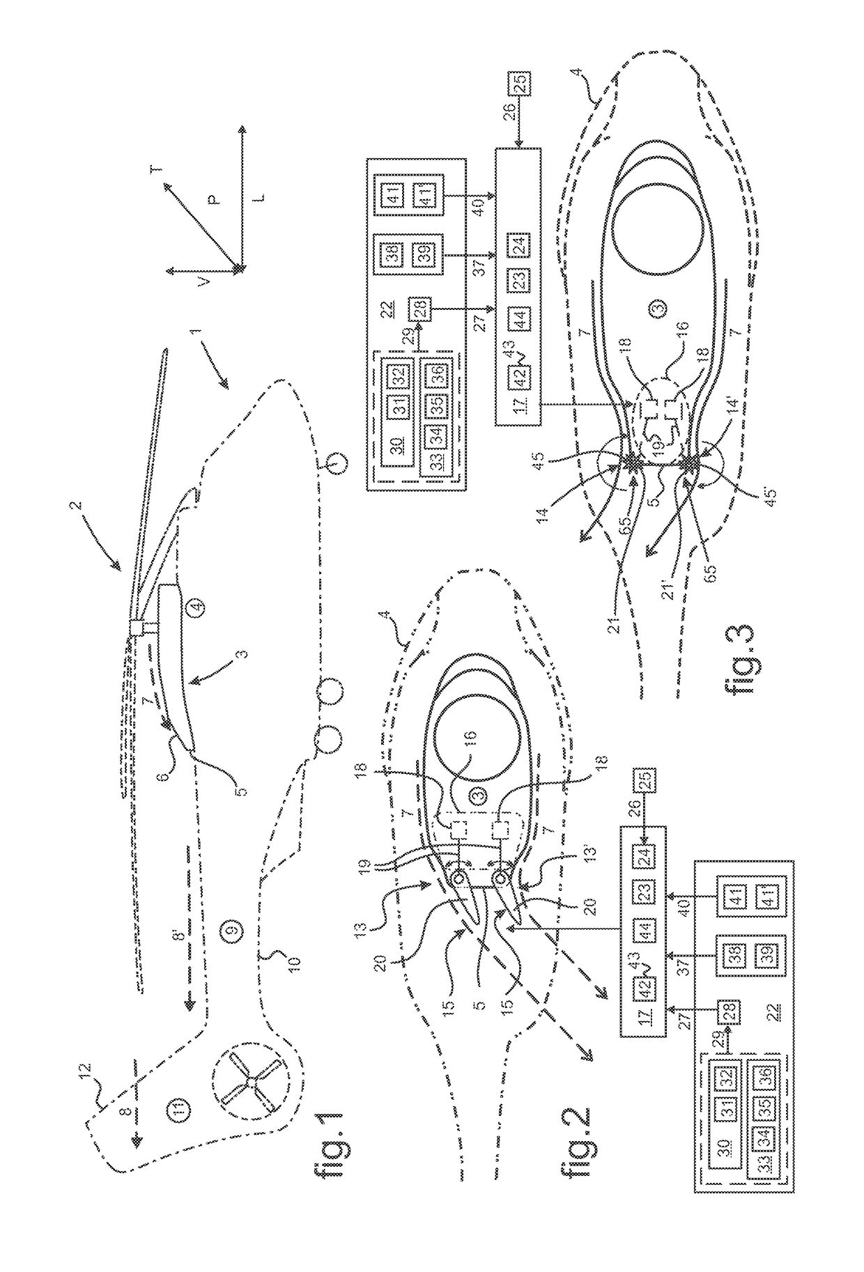
[0095]In FIG. 1, a rotorcraft 1 is conventionally fitted with a main rotor 2 of axis that is substantially vertical that provides the rotorcraft 1 with at least its lift, and possibly also its propulsion and / or guidance along its movement axes.

[0096]In its portion at the top relative to the vertical V orientation, the rotorcraft 1 is also fitted with a power plant providing the rotorcraft 1 with the mechanical power necessary for operation, in particular at least for driving the main rotor 2 in rotation.

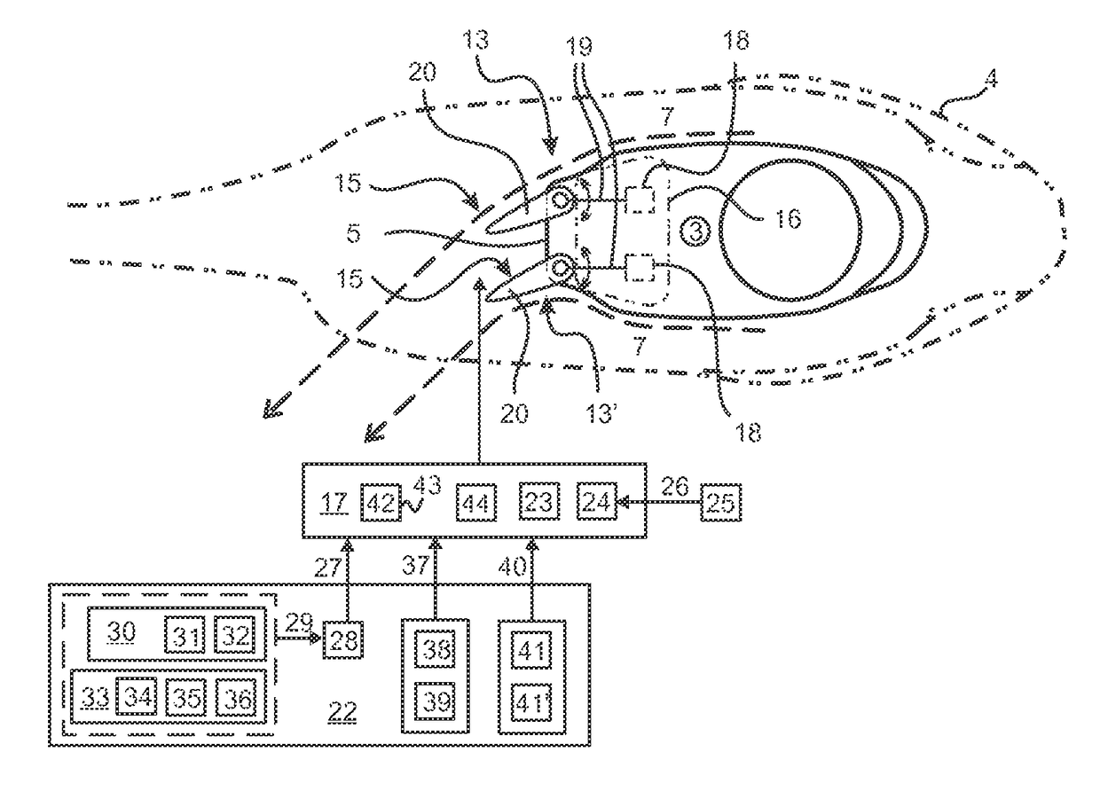
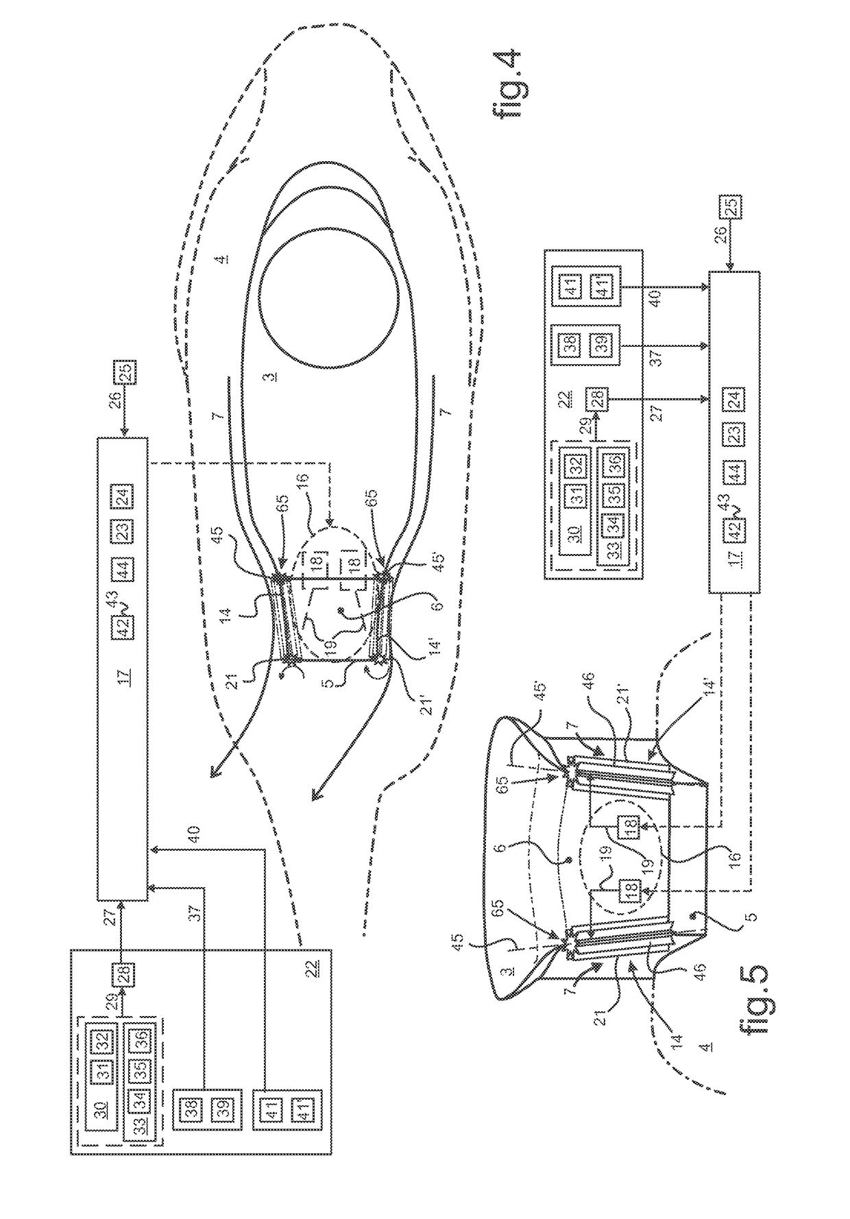
[0097]A fairing 3 for protecting a mechanism for operating the blades of the rotary wing constituted by the main rotor 2 is provided in conventional manner on top of a cover 4 for protecting the power plant. Said fairing 3 is typically arranged below the rotary wing of the main rotor 2 and it extends longitudinally in the longitudinally-extending direction L of the rotorcraft 1, conventionally considered as being between the front and the rear of the rotorcraft 1 when on the ground. ...


PUM


Abstract

A rotorcraft provided on top with a waterdrop-shaped fairing arranged below the rotary wing of a main rotor of the rotorcraft and overlying a cover covering a power plant of the rotorcraft. The trailing edge(s) of the fairing is / are provided with a respective movable member guiding a first stream of air flowing along the fairing and escaping from the trailing edge towards the rear of the rotorcraft in flight. By way of example, the movable member is arranged as a flap or as a bladed roller that may potentially be motor-driven as a function of the effects of the first stream of air on the behavior of the rotorcraft in flight.

Description

CROSS REFERENCE TO RELATED APPLICATION[0001]This application claims priority to French patent application No. FR 14 02463 filed on Oct. 31, 2014, the disclosure of which is incorporated in its entirety by reference herein.BACKGROUND OF THE INVENTION[0002](1) Field of the Invention[0003]The present invention relates to means for influencing the flow of air over the outside surfaces of rotorcraft. The present invention relates more particularly to a fairing conventionally arranged at the top of a rotorcraft being located under the rotary wing of a main rotor of substantially vertical axis and above a cover covering a power plant of the rotorcraft.[0004](2) Description of Related Art[0005]A rotorcraft is a rotary wing aircraft having one or more rotors, including at least a main rotor of substantially vertical axis arranged at the top of the rotorcraft. The main rotor typically provides the rotorcraft at least with lift, and in the specific circumstance of a helicopter, possibly also w...

Claims


Application Information

Patent Timeline
Patent Type & Authority Patents(United States)
IPC IPC(8): B64C11/00B64C13/16B64C27/02B64C27/04B64C27/06B64C7/00B64C27/54
CPCB64C7/00B64C13/16B64C27/06B64C27/04B64C27/02
Inventor ALFANO, DAVID
Owner EUROCOPTER
Why Eureka
Try Eureka