Method and apparatus for preparing a surface for bonding a material thereto

a technology of bonding material and surface, which is applied in the direction of mechanical apparatus, adhesive process with surface pretreatment, manufacturing tools, etc., can solve the problems of difficult control of the boundary between the masking surface, the difficulty of controlling the size and dimension of the surface to be prepared, and the time-consuming and laborious process of degreasing alone to prepare the surface. , to achieve the effect of reducing the time of surface preparation and improving the accuracy of the boundary pattern

Active Publication Date: 2018-03-20
SCHAUBLIN
View PDF38 Cites 0 Cited by
  • Summary
  • Abstract
  • Description
  • Claims
  • Application Information

AI Technical Summary

Benefits of technology

[0007]In one embodiment, the pattern consists of a series of protrusions and depressions. In another embodiment, this series of protrusions and depressions is extended to form lines. In another embodiment, the OAD is rapidly charged and discharged to create a series of points or dimples. In one embodiment, the formation of the pattern creates a shape, the dimensions of which are based on where, about coordinates within a plane, the pattern begins and ends. The formation of the patterns, using the OAD, controls the dimensions of the shape within 0.002 inches. Formation of the pattern in this manner eliminates the need for masking, greatly reducing surface preparation time and tediousness. Accuracy of the boundary of the pattern is also improved over prior art methods.

Problems solved by technology

However, degreasing alone does not, in most cases, prepare a surface for a bond of adequate peak load in peel tests.
However, the chemical etching procedure is cumbersome, tedious and time consuming.
However, control of the size and dimensions of the surface to be prepared and the boundaries between the surface to be prepared and the masked surface are difficult to control.

Method used


Image

  • Method and apparatus for preparing a surface for bonding a material thereto
  • Method and apparatus for preparing a surface for bonding a material thereto
  • Method and apparatus for preparing a surface for bonding a material thereto

Examples


Embodiment Construction

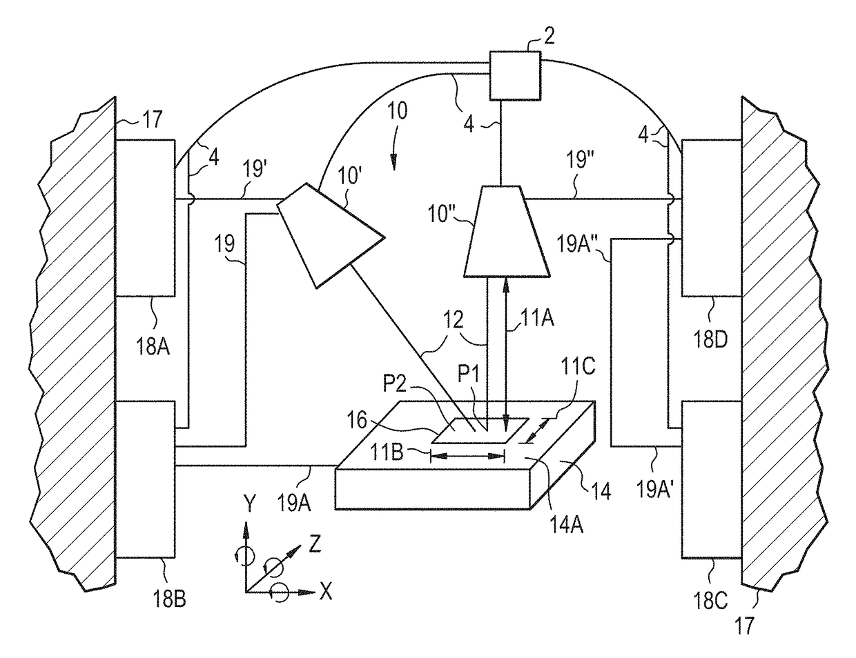
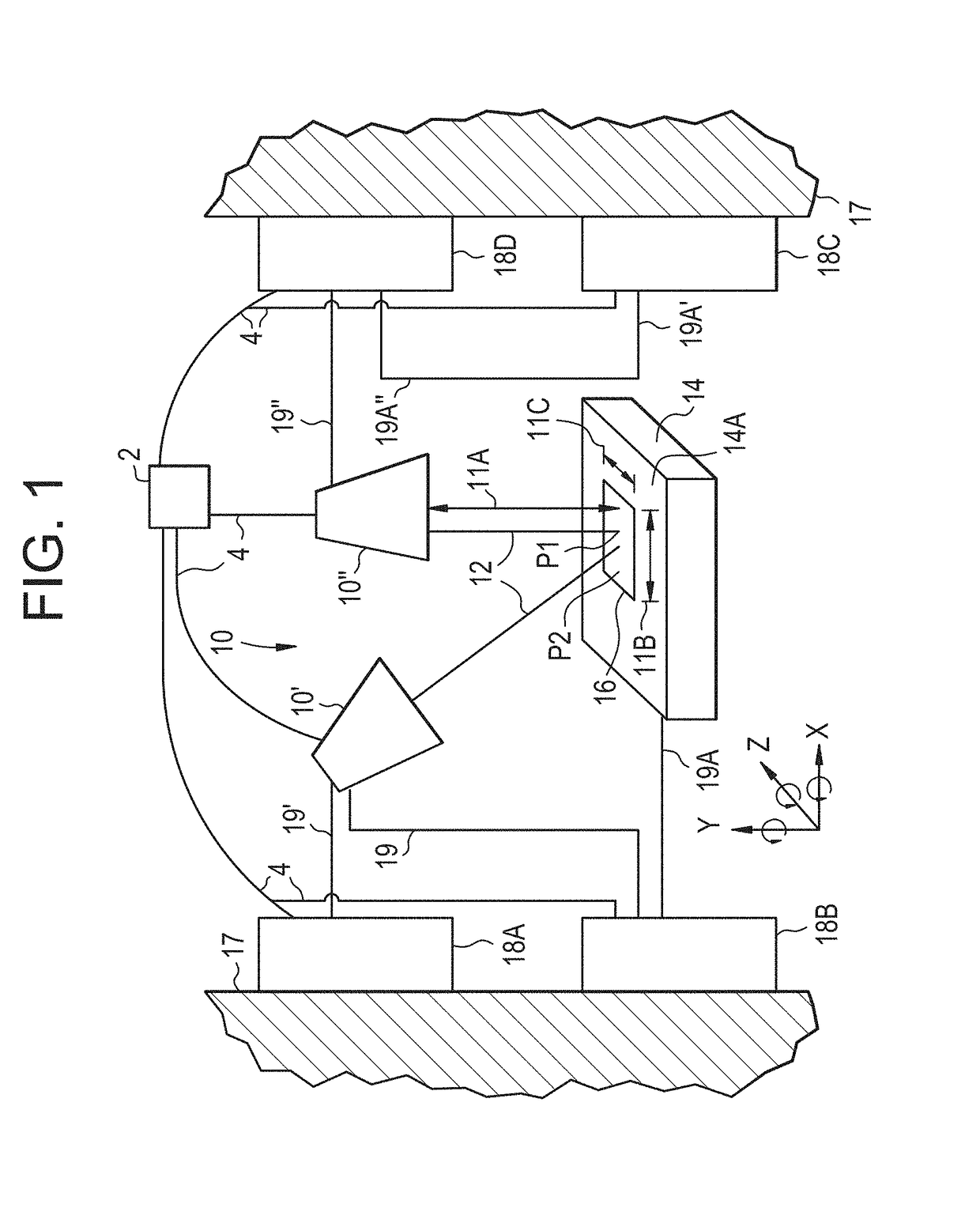
[0029]As shown in FIG. 1, an optical amplification system (OAS) is generally designated by the numeral 10. As described further herein, the OAS 10 emits beams of energy 12 to form a pattern 16 on a surface 14A (e.g., a flat surface, as shown) of a substrate 14 for bonding a material thereto (see element 24 in FIG. 4). In one embodiment, the OAS 10 includes two lasers and each of the beams of energy 12 are laser beams. However, the present invention is not limited in this respect, as other devices may be employed to form the pattern 16 on the surface 14A, such as, but not limited to, an electron beam emitter. While FIG. 1 shows a flat surface 14A, the present invention is not limited in this regard, as the surface 14A may be any suitable shape, including but not limited to arcuate, cylindrical (e.g., see FIG. 12) and / or spherical (e.g., see FIG. 14).

[0030]In one embodiment, the present invention relates to a method for preparing a surface 14A of a substrate 14 for bonding a material ...


PUM

PropertyMeasurementUnit
angleaaaaaaaaaa
angleaaaaaaaaaa
poweraaaaaaaaaa

Abstract

A method for preparing a surface of a substrate for bonding a material to the surface. The apparatus employed includes one or more optical amplification devices (OAD), one or more drivers, the substrate and a base. The one or more OAD and / or the substrate are moveably coupled to the one or more drivers. The one or more OAD is activated to emit a beam of energy. The one or more OAD and / or the substrate move relative to one another while the one or more OAD is activated. The movement of the one or more OAD and / or the substrate relative to one another forms (via the beam of energy) a pattern on the surface of the substrate. The pattern formed on the surface of the substrate allows the material to bond with a greater degree of adhesion.

Description

CROSS REFERENCE TO RELATED APPLICATIONS[0001]This application claims priority to U.S. Provisional Patent Application No. 61 / 982,916, filed Apr. 23, 2014, the subject matter of which is incorporated herein by reference in its entirety.FIELD OF THE INVENTION[0002]The present invention relates to a method for preparing a surface for bonding a material (e.g., a flexible liner) to the surface, and more particularly to the use of an optical amplification device such as a laser to form a pattern on the surface, thus enhancing the peak strength of the bond in peel testing as compared to other methods of surface preparation in which masking is not required. Similarly, the present invention relates to an apparatus for preparing a surface for bonding a material (e.g., a flexible liner) to the surface, and more particularly to an apparatus including the optical amplification device such as the laser, a substrate, one or more drivers moveably coupled to the optical amplification device and / or th...

Claims


Application Information

Patent Timeline
Patent Type & Authority Patents(United States)
IPC IPC(8): B23K26/36B23K26/00F16C43/00B32B38/00B32B37/18C09J5/02B23K26/362B32B37/00B23K26/361B32B37/12B23K103/00
CPCB32B37/0076B23K26/0006B23K26/0078B23K26/361B23K26/362B32B37/1292B32B38/0008C09J5/02F16C43/00B32B37/18C09J2400/166B23K2203/50C09J2205/31C09J2400/163B23K26/3584B23K2103/50C09J2301/416
Inventor BOURGOIS, LOUIS
Owner SCHAUBLIN
Why Eureka
Try Eureka