
Backchannel transmission adaptation

a backchannel transmission and serial data technology, applied in the field of adapting a transmitter sending serial data signals, can solve the problems of limiting quality, increasing the difficulty of the receiving ic to correctly interpret the data in the received signal, and affecting the clarity or fidelity of signals

Active Publication Date: 2018-03-20
ALTERA CORP
View PDF12 Cites 2 Cited by
  • Summary
  • Abstract
  • Description
  • Claims
  • Application Information

AI Technical Summary

Benefits of technology

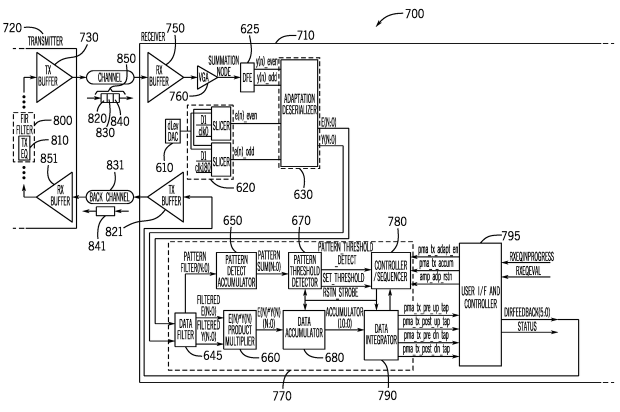
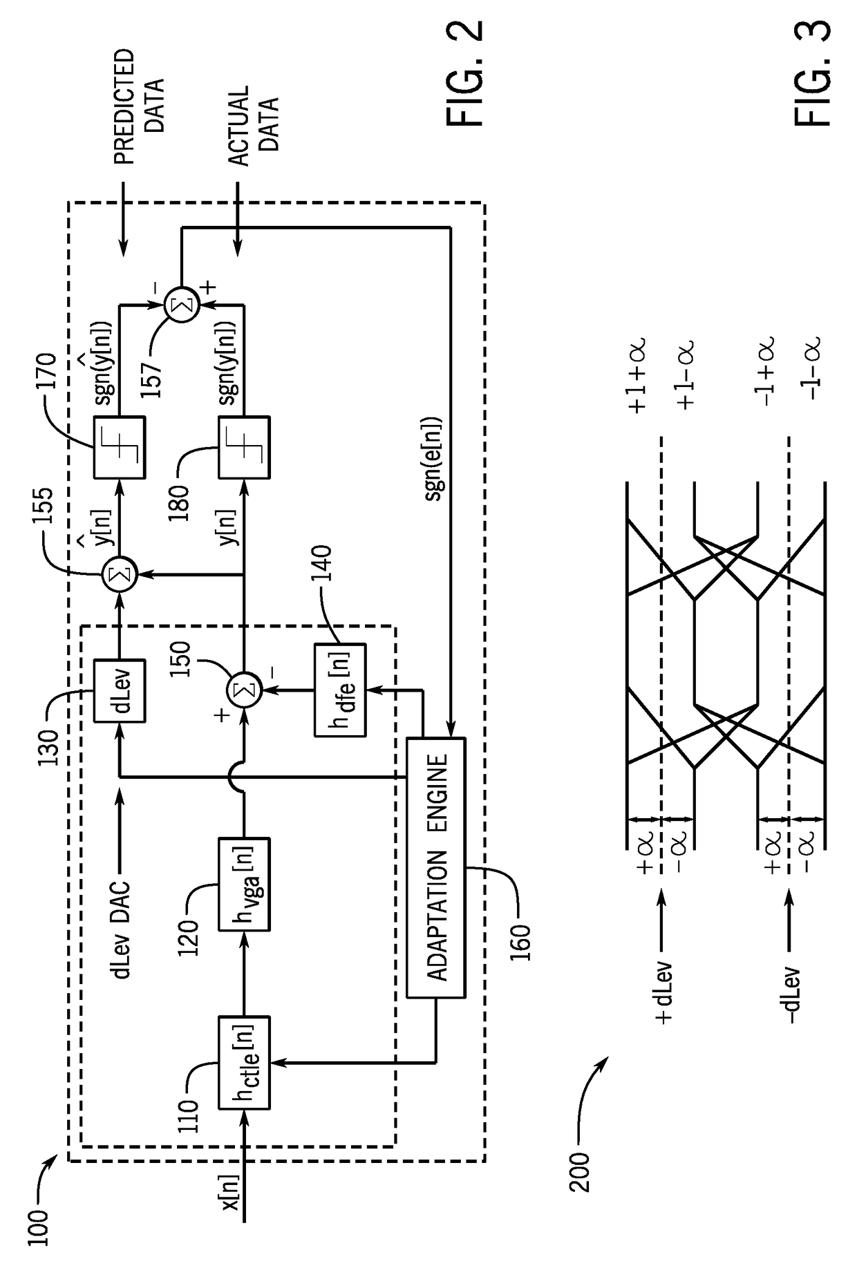
The present patent relates to a system and method for improving the quality of signals by reducing inter-symbol interference (“ISI”) in received signals. The system includes a transmitter equalization partial response adaptation engine that determines a transmitter adjustment based on error in the received signal. One or more components of the receiver are then frozen to prevent changes in settings. The transmitter adjusts its settings based on the transmitter adjustment and sends a signal to the receiver to unfreeze it. The technical effect of this system and method is to improve signal quality by reducing ISI contributions in the received signal.

Problems solved by technology

One problem when using high speed serial data signals is that the signals may be subject to loss of clarity or fidelity when propagating through a medium used to transmit the signals.
Signal degradation (e.g., as described above from a programmable logic IC transmitting that signal through a transmission medium to another programmable logic IC receiving the signal) increases the difficulty of the receiving IC to correctly interpret the data in the received signal.
This static setting may limit the quality of the results of signal conditioning adaptive recovery circuitry and may also make performance prone to environmental variations, such as variations in temperature, voltage, or noise.
Moreover, using half rate DFE structures may require an excessive number of high speed multipliers and sense amplifiers (that may cause excessive loading on the summation node, increase intrinsic kickback noise generated on the summation node, and increase cost and area required for the receiver), as well as high speed multiplexers.

Method used


Image

  • Backchannel transmission adaptation
  • Backchannel transmission adaptation
  • Backchannel transmission adaptation

Examples


Embodiment Construction

[0025]One or more specific embodiments will be described below. In an effort to provide a concise description of these embodiments, not all features of an actual implementation are described in the specification. It may be appreciated that in the development of any such actual implementation, as in any engineering or design project, numerous implementation-specific decisions must be made to achieve the developers' specific goals, such as compliance with system-related and business-related constraints, which may vary from one implementation to another. Moreover, it may be appreciated that such a development effort might be complex and time consuming, but would nevertheless be a routine undertaking of design, fabrication, and manufacture for those of ordinary skill having the benefit of this disclosure.

[0026]Techniques for reducing inter-symbol-interference (ISI) in a high speed serial data signal by adjusting a transmitter sending the signal are disclosed. A transmitter equalization ...


PUM


Abstract

Receiver circuitry for receiving a data signal includes summation node circuitry that predicts an error value of the received data signal. The receiver circuitry also includes adaptation engine circuitry coupled to the summation node circuitry. The adaptation engine circuitry determines a transmitter adjustment based on the error value and sends a freeze signal to one or more components of the receiver to cause the receiver to continue operating without changing current settings of the one or more components. The receiver circuitry further includes a user interface and sequence controller, coupled to the adaptation engine circuitry, wherein the user interface and sequence controller sends a signal indicative of the transmitter adjustment to the transmitter.

Description

RELATED PATENT[0001]This patent application incorporates by reference in its entirety U.S. Pat. No. 9,264,276 entitled “ADAPTATIONS FOR PARTIAL RESPONSE SUMMATION NODE EMBEDDED FPGA TRANSCEIVER” filed on Nov. 14, 2014.BACKGROUND[0002]This disclosure relates generally to improving signal quality by recovering data from a serial data signal received by circuitry, and more particularly to adapting a transmitter sending the serial data signal based on receiving the serial data signal.[0003]This section is intended to introduce the reader to various aspects of art that may be related to various aspects of the present disclosure, which are described and / or claimed below. This discussion is believed to be helpful in providing the reader with background information to facilitate a better understanding of the various aspects of the present disclosure. Accordingly, it may be understood that these statements are to be read in this light, and not as admissions of prior art.[0004]Communicating d...

Claims


Application Information

Patent Timeline
IPC IPC(8): H04L25/03H04B1/04
CPCH04L25/03057H04B1/04H04L25/03343H04B1/0475H04B2001/0408
Inventor WALLICHS, GARY BRIANCHAN, ALLEN K.WENG, KUO-YIN
Owner ALTERA CORP
Learn More