Heat exchange system

a heat exchanger and heat exchange technology, applied in the direction of lighting and heating apparatus, tubular elements, stationary conduit assemblies, etc., can solve the problems of difficult to improve heat exchange performance, difficult to improve pressure resistance quality, increase the number of louvers, etc., to improve the heat exchange performance of the heat exchanger, improve the strength of the tube and the fin, and improve the flow of cooling air

Active Publication Date: 2018-03-27
HANON SYST
View PDF11 Cites 2 Cited by
  • Summary
  • Abstract
  • Description
  • Claims
  • Application Information

AI Technical Summary

Benefits of technology

[0026]According to the heat exchanger according to the embodiment of the present invention, the center bank may be formed to be eccentric based on the center in the width direction of the fin and the number of louvers of both sides may be formed to be different based on the center bank to improve the flow of cooling air, thereby improving heat radiation performance of the heat exchanger.
[0027]Further, the strength supporting the tube and the fin may be improved by the center bank eccentrically formed to improve the durability against the flow pressure of the cooling air.

Problems solved by technology

However, in order to form the louver 6 by cutting and then folding the fin 5, the number of louvers 6 of both sides needs to be symmetrically formed to each other based on the center bank 5a in terms of manufacturing characteristics and since a width of the fin 5 is limited, it is difficult to increase the number of louvers and thus it is difficult to improve heat exchange performance.
However, it is difficult to improve the pressure resisting quality due to the cooling air while improving the heat exchange performance.

Method used


Image

  • Heat exchange system
  • Heat exchange system
  • Heat exchange system

Examples


Embodiment Construction

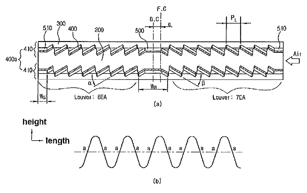
[0087]1000: (The present invention) Heat exchanger[0088]100: Header tank[0089]110: Inlet pipe[0090]120: Outlet pipe[0091]200: Tube[0092]210: Reinforcing rib[0093]300: fin[0094]310: Display unit[0095]400: Louver[0096]400a: Louver column[0097]410: First louver column[0098]420: Second louver column[0099]500: Center bank[0100]510: Side support part[0101]WB: Width of center bank[0102]WS: Width of side support part[0103]WO: Overlapping width of center banks[0104]PL: Pitch of louver[0105]α: Angle of louver of side where the number of louvers is small[0106]β: Angle of louver of side where the number of louvers is large[0107]F.C: Central line of fin[0108]B.C: Central line of center bank[0109]LB: Distance between central lines of center bank[0110]e: Eccentricity


PUM


Abstract

Provided is a heat exchanger, and more particularly, a heat exchanger including a pair of header tanks formed in parallel, spaced apart from each other by a predetermined distance, a plurality of tubes having both ends fixed to the pair of header tanks to form a channel for a heat exchange medium; a plurality of fins fixed to abut between the tubes, and a plurality of louvers formed at the fins to contact air passing through the circumference of the fins, in which the louvers are formed to be asymmetrical to each other based on a center in a width direction of the fin or louver columns formed at one side or the other side of the fin in an asymmetrical form are alternately formed in a length direction of the fins to improve a flow of cooling air, thereby improving a heat radiation performance.

Description

CROSS-REFERENCE TO RELATED APPLICATIONS[0001]This application is a United States national phase application based on PCT / KR2014 / 000881 filed Jan. 29, 2014, which claims the benefit of Korean Patent Application No. 10-2013-0011729 Feb. 1, 2013 and 10-2014-0010617 dated Jan. 28, 2014.TECHNICAL FIELD[0002]The present invention relates to a heat exchanger, and more particularly, to a heat exchanger including a pair of header tanks formed in parallel, spaced apart from each other by a predetermined distance, a plurality of tubes having both ends fixed to the pair of header tanks to form a channel for a heat exchange medium; a plurality of fins fixed to abut between the tubes, and a plurality of louvers formed at the fins to contact air passing through the circumference of the fins, in which the louvers are formed to be asymmetrical to each other based on a center in a width direction of the fin or louver columns formed at one side or the other side of the fin in an asymmetrical form are ...

Claims


Application Information

Patent Timeline
Patent Type & Authority Patents(United States)
IPC IPC(8): F28D1/04F28F1/02F28F1/12F28F1/04F28F1/32F28D1/053F28D1/02F28D21/00
CPCF28D1/0233F28D1/05358F28D1/05391F28F1/045F28F1/128F28F1/325F28F1/022F28D2021/0094
Inventor HAN, JI HUNKIM, JAE YONGKIM, HYUKMIN, EUN GIJEON, SEONG-OHJEONG, SUN AN
Owner HANON SYST
Why Eureka
Try Eureka